Screw-type dental implant

a dental implant and screw-type technology, applied in dental implants, dental surgery, medical science, etc., can solve problems such as bone receding, osseointegration around the collar, and sometimes occurring problems

Active Publication Date: 2007-12-27
OCO BIOMEDICAL INC
View PDF30 Cites 60 Cited by
  • Summary
  • Abstract
  • Description
  • Claims
  • Application Information

AI Technical Summary

Benefits of technology

[0009] The invention is directed to a screw-type dental implant including a self-tapping, tapered body portion, with externally threaded, auger-like threads. A divergent collar extends from the body portion and is partially threaded with a mini-thread. The implant includes an abutment on top of the collar portion. The abutment has one or more concave grooves extending longitudinally for engaging with a tool for inserting the implant into an opening formed in the bone tissue to receive the implant. The tapered threaded body portion of the implant ends in a blunt tip. The inner diameter of the threads of the tapering portion becomes progressively less, yet the auger-like threads provide a deep thread at the tip of the implant. The preferred embodiment is a one-piece implant, however, an alternative embodiment is a two-piece implant wherein the abutment is screwed into the body portion. In the two-piece implant, the body portion has a cavity and internal threads designed to engage an abutment with a compatible outer shape and external threads. The two-piece embodiment preferably utilizes the threads and a taper to join the body portion and the abutment. Finally, the invention is also directed to a method of placing a dental implant, whether a one-piece or two-piece implant.

Problems solved by technology

Various problems exist with the present generation of implant bodies utilized by dentists and surgeons.
Additionally, problems sometimes occur with osseointegration around the collar portion of the implant.
Another problem relates to the period of time required for the bone to bond sufficiently with the implant such that the artificial crown can be mounted and the implant may be used to fully restore oral function.
Because an unnecessarily large portion of the bone is exposed to air, it may cause the bone to recede, sometimes as much as one to two millimeters, which in turn has a negative effect.

Method used


Image

  • Screw-type dental implant
  • Screw-type dental implant
  • Screw-type dental implant

Examples


Embodiment Construction

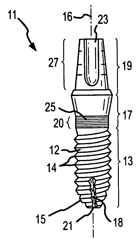
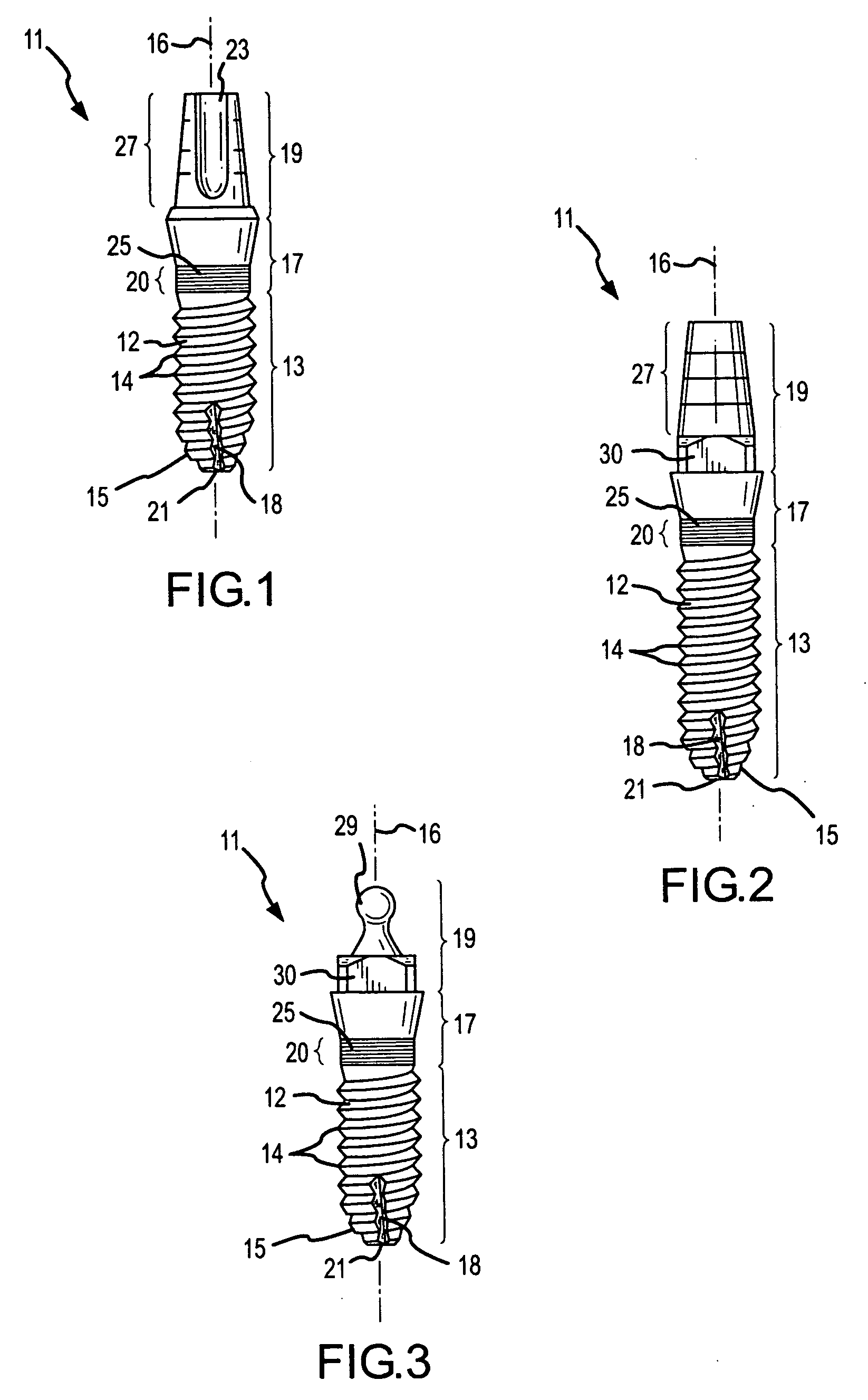
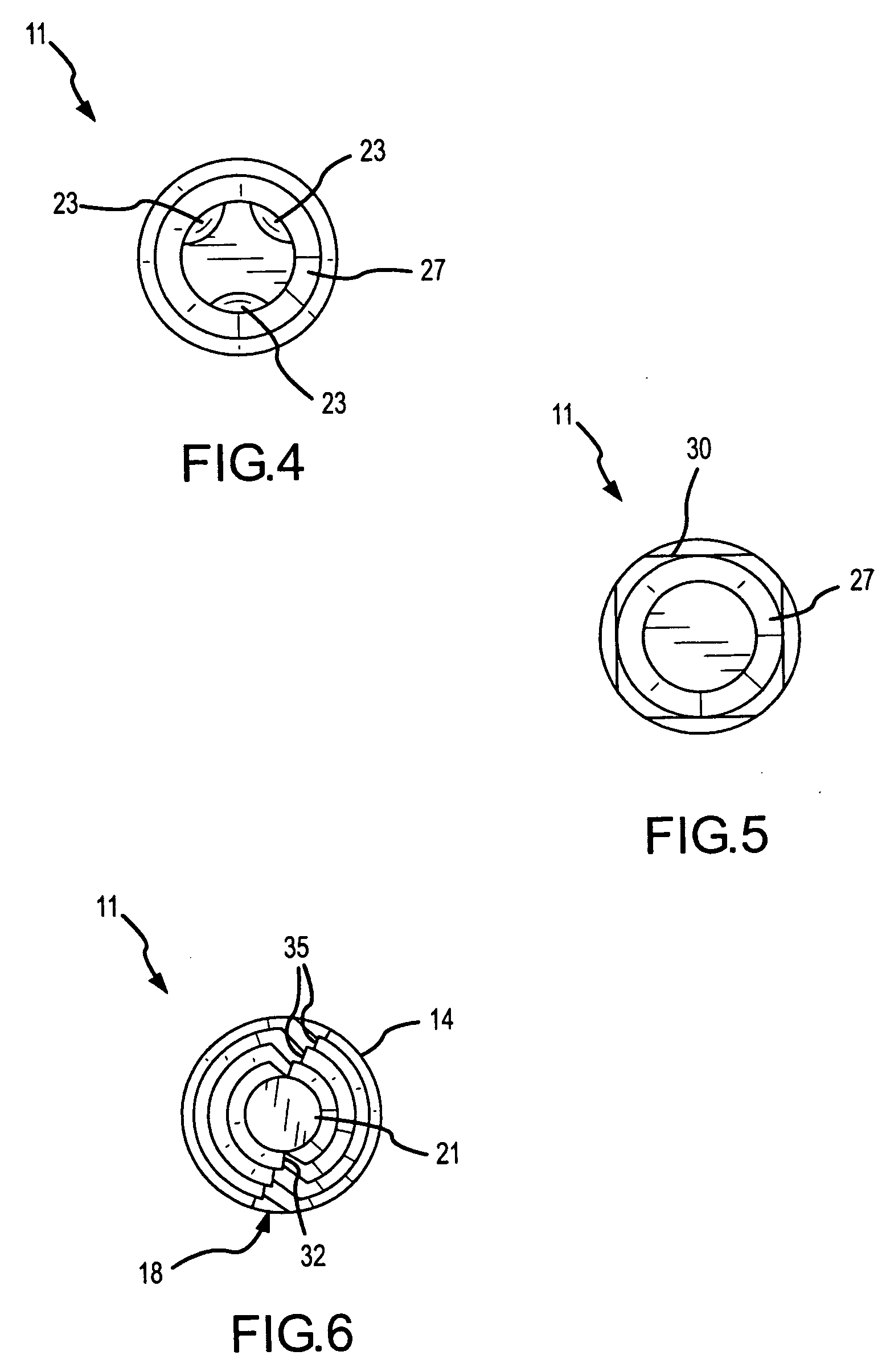
[0020] In a preferred embodiment, the invention is a one-piece screw-type dental implant that includes an externally threaded body portion with auger-like threads that thread into the bone, an intermediate divergent collar, and an abutment for securing a single tooth, multiple teeth, or a denture to the jaw bone. The bottom of the apical end of the body portion preferably has two opposing longitudinal grooves to aid in the implant's self-tapping as it is driven into the bone and also to aid in the removal of bone and blood from the osteotomy hole as the implant is inserted. The tip (apical end) has a blunt, preferably flat, surface, approximately the same diameter as the tip of the pilot drill such that when the implant reaches the bottom of the predrilled hole it will not burrow deeper than the pilot hole. The inner diameter of the auger-like threads on the tapering portion decreases, but the auger-like threads do not taper to a zero-depth thread. The foregoing provides a deep thre...


PUM


Abstract

A dental implant apparatus consisting of an auger-like lower threaded portion that is screwed into the bone. It includes a divergent intermediate collar with mini-threads for engaging the cortical bone, and a tapered abutment for fixed tooth replacement or a ball-like snap attachment to secure removable dentures. The apical end of the device has a tapered portion with a blunt tip that condenses the medullar bone, which in combination with the divergent collar engaging and wedging into the cortical bone, provides a dual stabilization structure that can be immediately loaded or placed in light function by cementing on a temporary crown or bridge or by lightly attaching a removable full or partial denture.

Description

FIELD OF THE INVENTION [0001] This invention relates generally to dental implants, and more specifically to a screw-type dental implant having an improved configuration to more securely affix the implant to the bone structure in a patient's mouth at the time the implant is placed. BACKGROUND OF THE INVENTION [0002] Dental implants are used in place of missing, or extracted, teeth, whether due to accident or disease, and have the ability to perform the functions of natural teeth. A dental implant is used as an artificial root (support), with an artificial crown (prosthesis) placed on the artificial root after integration with the jawbone. An abutment serves as a spacer between the support and the prosthesis, with the implant serving as the base support for the abutment and final prosthesis in an attempt to restore normal oral function. Alternatively, the prosthesis may be secured directly to the support without utilizing a spacer. [0003] Generally, an implant is surgically placed in ...

Claims


Application Information

Patent Timeline
Patent Type & Authority Applications(United States)
IPC IPC(8): A61C8/00
CPCA61C8/0025A61C8/005A61C8/006A61C8/0089A61C8/0069A61C8/0071A61C8/0066
Inventor D'ALISE, DAVID D.
Owner OCO BIOMEDICAL INC
Why Eureka
Try Eureka