Fan variable area nozzle for a gas turbine engine fan nacelle

a gas turbine engine and variable area technology, applied in the field of gas turbine engines, can solve the problems of increased complexity, high cost, and increased cost of variable area nozzle structures, and achieve the effects of low cost, high efficiency, and high efficiency

Active Publication Date: 2008-01-03
RTX CORP
View PDF29 Cites 27 Cited by
  • Summary
  • Abstract
  • Description
  • Claims
  • Application Information

AI Technical Summary

Benefits of technology

[0008]In operation, the actuator assembly rotates the synchronizing ring circumferentially about the engine longitudinal centerline axis. The slider block assembly moves within the slot such that a rod which extends from the hinge beam translates slider block radial motion to a rod tangential moment about the hinge. The resulting flap assembly moment about the flap hinge varies the diameter of the flap assembly and thus the annular fan exit area within the fan nacelle. By adjusting the FVAN, engine thrust and fuel economy are maximized during each flight regime.
[0009]The present invention therefore provides an effective, relatively inexpensive variable area nozzle for a gas turbine engine fan nacelle.

Problems solved by technology

In combat aircraft, the necessity of high performance requires the expense, weight, and increased complexity of a variable area nozzle structure through which all exhaust is directed.
However, such considerations have precluded the incorporation of a variable area nozzle for the fan air of a turbofan gas turbine engine propulsion system typical of commercial and military transport aircraft.

Method used


Image

  • Fan variable area nozzle for a gas turbine engine fan nacelle
  • Fan variable area nozzle for a gas turbine engine fan nacelle
  • Fan variable area nozzle for a gas turbine engine fan nacelle

Examples


Embodiment Construction

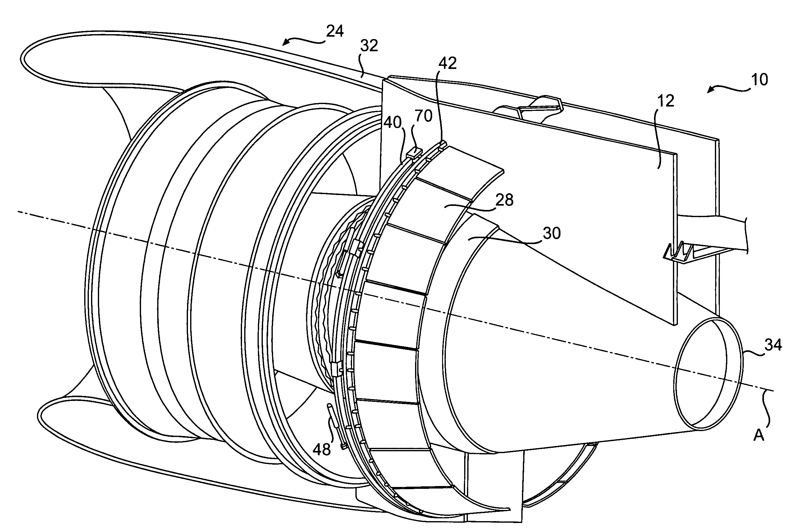
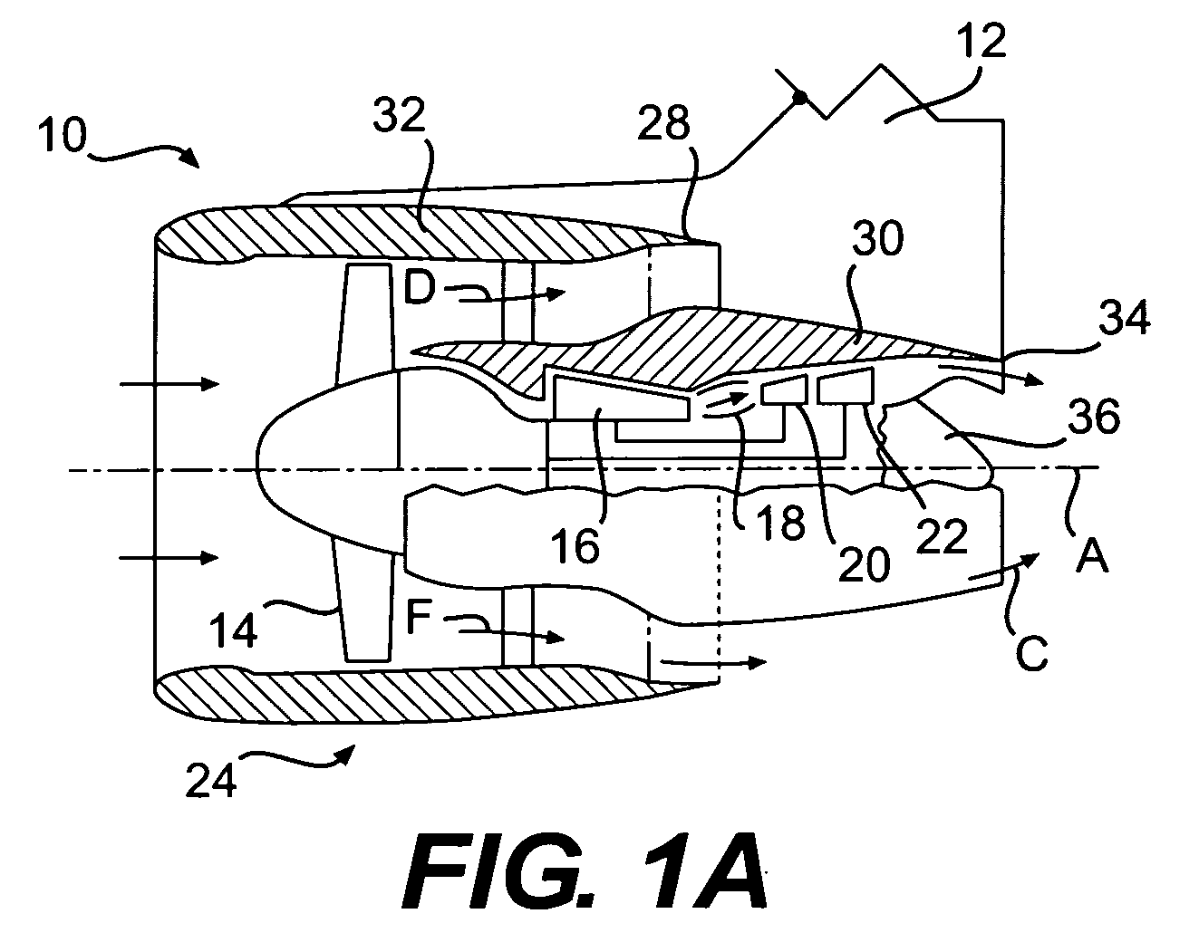
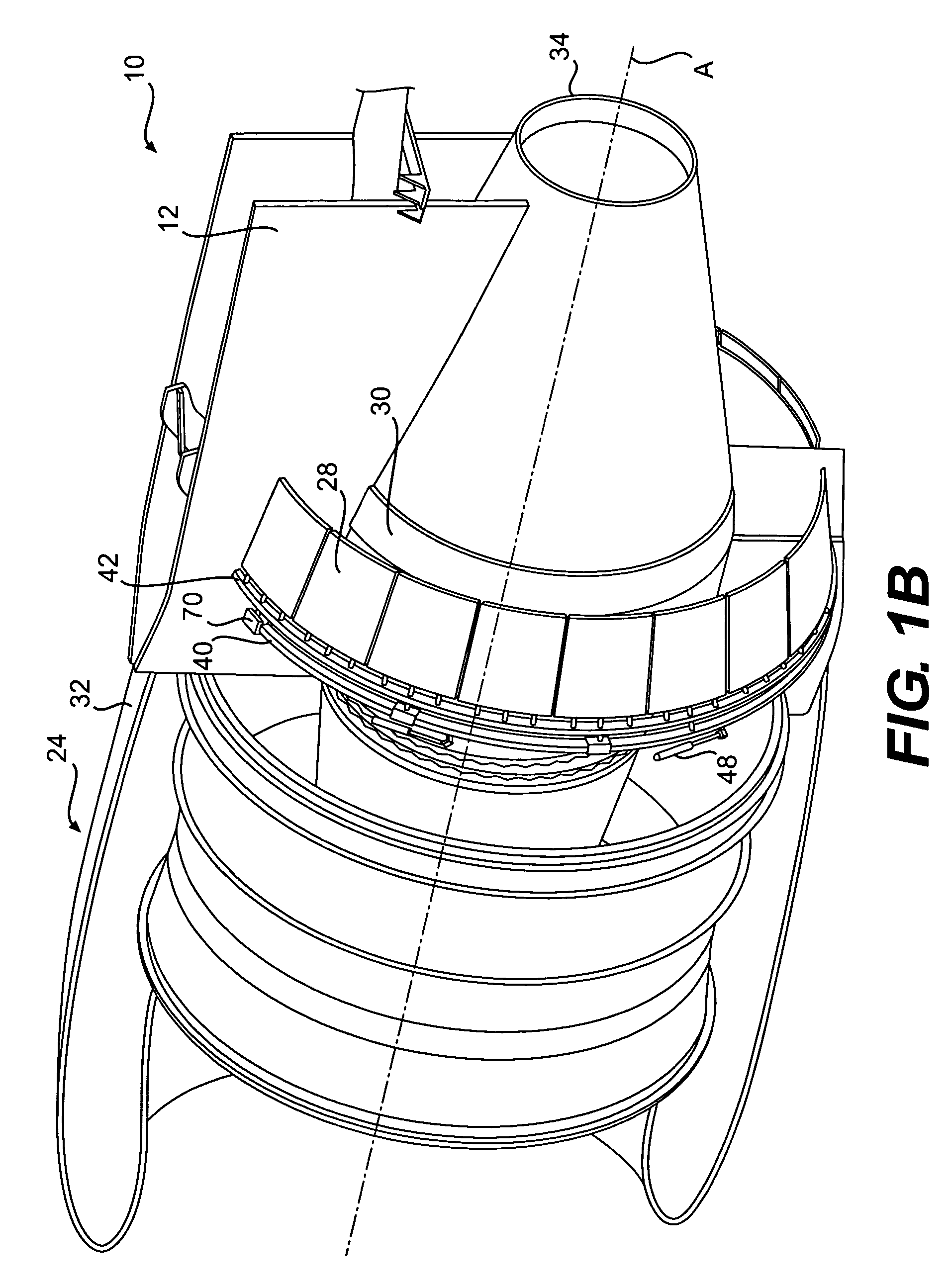
[0022]FIG. 1A illustrates a general partial fragmentary view of a gas turbofan engine 10 suspended from an engine pylon 12 as typical of an aircraft designed for subsonic operation. The engine 10 is preferably a high-bypass turbofan aircraft engine. The engine 10 typically includes in serial flow communication a fan 14 with a low pressure compressor, a high pressure compressor 16, an annular combustor 18, high pressure turbine 20, and low pressure turbine 22. During operation, air is pressurized in the compressor and mixed with fuel in the combustor for generating hot combustion gases which flow through the high and low pressure turbines that extract energy therefrom. The high pressure turbine powers the compressor through a shaft therebetween, and the low pressure turbine powers the fan through another shaft therebetween.

[0023]The exemplary turbofan engine 10 is in the form of a high bypass ratio engine mounted within a nacelle assembly 24 in which most of the air pressurized by th...


PUM


Abstract

A fan variable area nozzle (FVAN) selectively rotates a synchronizing ring relative the static ring to adjust a flap assembly through a linkage to vary an annular fan exit area through which fan air is discharged. By adjusting the FVAN, engine thrust and fuel economy are maximized during each flight regime.

Description

BACKGROUND OF THE INVENTION[0001]The present invention relates to a gas turbine engine, and more particularly to a turbofan gas turbine engine having a variable area nozzle structure within the fan nacelle thereof.[0002]In an aircraft turbofan engine, air is pressurized in a compressor and mixed with fuel in a combustor for generating hot combustion gases which flow downstream through turbine stages that extract energy therefrom. A high pressure turbine powers the compressor, and a low pressure turbine powers a fan disposed upstream of the compressor.[0003]Combustion gases are discharged from the core engine through a core exhaust nozzle, and fan air is discharged through an annular fan exhaust nozzle defined at least partially by a nacelle surrounding the core engine. A majority of propulsion thrust is provided by the pressurized fan air discharged through the fan exhaust nozzle, the remaining thrust provided from the combustion gases discharged through the core exhaust nozzle.[000...

Claims


Application Information

Patent Timeline
Patent Type & Authority Applications(United States)
IPC IPC(8): F02K1/00
CPCF01D17/141F02K1/06F02K1/1207F02K1/15F02K3/06F02K3/075F05D2260/50F05D2270/60F05D2270/62
Inventor HANSON, RUSSELL B.
Owner RTX CORP
Why Eureka
Try Eureka