Dirt mitigation in a gas turbine engine

a gas turbine engine and gas turbine technology, applied in the field of engine systems, can solve the problems of affecting affecting the performance of the engine, so as to achieve the effect of reducing the life of the engine, reducing the excess fuel consumption, and reducing the amount of dust, dirt and debris

Active Publication Date: 2020-04-30
RTX CORP
View PDF4 Cites 8 Cited by
  • Summary
  • Abstract
  • Description
  • Claims
  • Application Information

AI Technical Summary

Benefits of technology

[0020]A technical effect of the apparatus, systems and methods is achieved by providing dirt mitigation in a gas turbine engine as described herein.

Problems solved by technology

Engines, such as gas turbine engines, can operate in unclean environments that result in ingestion of dust, dirt, and debris.
The particulate matter can result in degraded performance, such as thrust reduction, excess fuel consumption, and possible component life reduction.
Regular engine cleaning can remove environmental particulate matter; however, cleaning and servicing based on a predetermined time interval may result in premature or late actions relative to the actual condition of an engine.

Method used


Image

  • Dirt mitigation in a gas turbine engine
  • Dirt mitigation in a gas turbine engine
  • Dirt mitigation in a gas turbine engine

Examples


Embodiment Construction

[0030]A detailed description of one or more embodiments of the disclosed apparatus and method are presented herein by way of exemplification and not limitation with reference to the Figures.

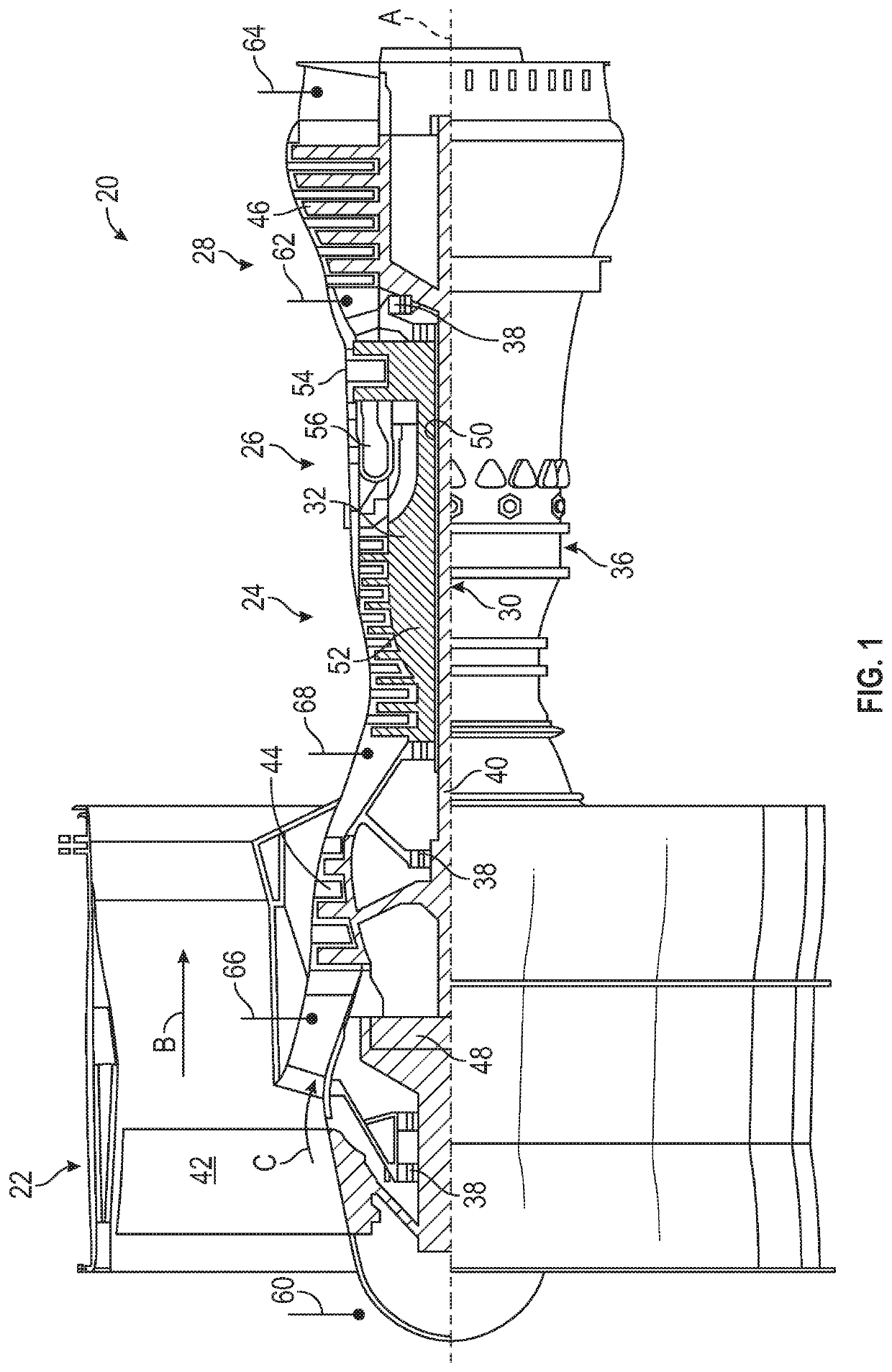
[0031]FIG. 1 schematically illustrates a gas turbine engine 20. The gas turbine engine 20 is disclosed herein as a two-spool turbofan that generally incorporates a fan section 22, a compressor section 24, a combustor section 26 and a turbine section 28. The fan section 22 drives air along a bypass flow path B in a bypass duct, while the compressor section 24 drives air along a core flow path C for compression and communication into the combustor section 26 then expansion through the turbine section 28. Although depicted as a two-spool turbofan gas turbine engine in the disclosed non-limiting embodiment, it should be understood that the concepts described herein are not limited to use with two-spool turbofans as the teachings may be applied to other types of turbine engines including three-spool a...


PUM


Abstract

An aspect includes a dirt mitigation system for a gas turbine engine. The dirt mitigation system includes a plurality of bleeds of the gas turbine engine and a control system configured to determine a particulate ingestion estimate indicative of dirt ingested in the gas turbine engine. The control system is further configured to determine one or more operating parameters of the gas turbine engine and alter a bleed control schedule of the gas turbine engine to purge at least a portion of the dirt ingested in the gas turbine engine through one or more of the bleeds of the gas turbine engine based on the particulate ingestion estimate and the one or more operating parameters.

Description

BACKGROUND[0001]The subject matter disclosed herein generally relates to engine systems and, more particularly, to a method and apparatus for dirt mitigation in a gas turbine engine.[0002]Engines, such as gas turbine engines, can operate in unclean environments that result in ingestion of dust, dirt, and debris. Particulate matter can accumulate within an engine as it operates over a period of time. The particulate matter can result in degraded performance, such as thrust reduction, excess fuel consumption, and possible component life reduction. Regular engine cleaning can remove environmental particulate matter; however, cleaning and servicing based on a predetermined time interval may result in premature or late actions relative to the actual condition of an engine.BRIEF DESCRIPTION[0003]According to one embodiment, a dirt mitigation system for a gas turbine engine is provided. The dirt mitigation system includes a plurality of bleeds of the gas turbine engine and a control system...

Claims


Application Information

Patent Timeline
Patent Type & Authority Applications(United States)
IPC IPC(8): F02C9/18F02C7/052F02C6/08F02C9/44F02K3/075F04D27/02
CPCF04D27/0215F02C9/18F05D2260/607F05D2260/606F02C6/08F02K3/075F02C7/052F02C9/44F04D29/70F04D27/001F01D25/002B64D2045/0085Y02T50/60
Inventor HANLON, CHRISTOPHER J.KRENZER, JAMES F.ROSE, BECKY E.ZELESKY, MARK F.
Owner RTX CORP
Why Eureka
Try Eureka