Method and system for improving fuel economy and reducing emissions of internal combustion engines

a technology of internal combustion engine and combustion engine, which is applied in the direction of fuel system, fuel supply apparatus, non-fuel substance addition to fuel, etc., can solve the problems of lower overall fuel economy, lower overall fuel economy and efficiency, and higher greenhouse gas emissions that vary, so as to achieve a wide range of application

Active Publication Date: 2019-04-09
DYNACERT INC
View PDF65 Cites 9 Cited by
  • Summary
  • Abstract
  • Description
  • Claims
  • Application Information

AI Technical Summary

Benefits of technology

[0010]It is therefore an objective of the present invention to provide different ratios and volumes of hydrogen and oxygen gas to the air-intake of internal combustion engines to maximize the fuel economy and / or minimize emissions over a wide range of operating conditions.
[0051]Preferably, the monitoring and control system further comprises a recalibrator to recalibrate the engine's reaction to oxygen in the exhaust so as to improve the impact of said monitoring and control system on fuel economy, such recalibrator including a specialized circuit that modifies readings from one or more oxygen sensors, a means of adjusting the oxygen reading, or engine ECM software changes that accomplish same.

Problems solved by technology

However, EGR systems have not provided all the benefits expected as they have been mechanically unreliable and have also resulted in lower overall fuel economy.
With economic conditions requiring relatively stable amounts of energy demand per year (e.g. haulage (tons-miles) for freight, electrical power (watt hours) for power generators), the introduction of these “emission technologies” (EGR, and selective catalytic reduction “SCR”) has generally led to lower overall fuel economy and efficiency, and therefore higher greenhouse gas emissions that vary directly with fuel usage (i.e. carbon content in the diesel fuel or heavy fuel oil).
These technologies have also increased the cost of engines and the annual operating cost of diesel truck owners or power generators due to higher fuel usage, higher maintenance costs, and higher running costs to support the emissions technologies (e.g. particulate filters, urea for SCR etc.).
The energy required to produce hydrogen from the engine fuel with an “on demand” electrolysis system, however, exceeds the energy content available from the combustion of the hydrogen and there is some controversy about the benefits of such systems.
However, this work demonstrated that relatively high volumes of H2 / O2 gas are required to significantly reduce fuel consumption.

Method used


Image

  • Method and system for improving fuel economy and reducing emissions of internal combustion engines
  • Method and system for improving fuel economy and reducing emissions of internal combustion engines
  • Method and system for improving fuel economy and reducing emissions of internal combustion engines

Examples


Embodiment Construction

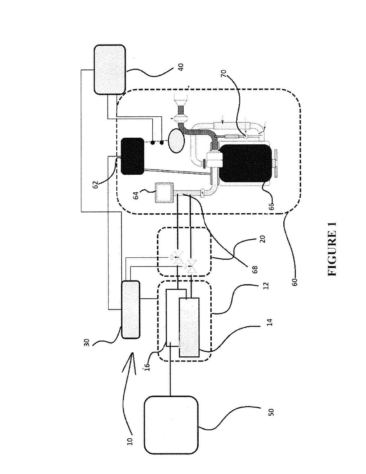
[0067]FIG. 1 is a schematic drawing showing the basic elements of the monitoring and control system 10 according to the present invention and their integration into an existing or new diesel engine system although, as highlighted, the inventive system is equally suitable for all combustion engines operating on carbon-based fuels. Specifically, the invention requires a source 12 of pure or almost pure (at least 90%) H2, shown in FIG. 1 as item 16, and O2, shown in FIG. 1 as item 14. These preferably include on-board or local, on-demand water electrolysis devices (wet or dry technology) or bulk storage or any other source. These gases are metered at specific ratios and volumes by metering device 20 and depending on control logic 30 that utilizes operating conditions received, for example, from the engine electronic control module (“ECM”) 62 including for example, engine load, engine rotations per minute (RPMs) and other readily available and independently assessed engine data from the...


PUM


Abstract

A method and system for improving the fuel economy and lowering the emissions of internal combustion engines by injecting predetermined amounts and ratios of on-board or locally generated hydrogen and oxygen to the engine's air intake and varying the gas addition volume and hydrogen / oxygen ratio as a function of the operating conditions, e.g., in line with the instant engine load.

Description

CROSS-REFERENCE TO RELATED APPLICATION[0001]This national application claims priority from International Patent Application No. PCT / CA2013 / 000737, filed on Aug. 22, 2013 which claimed priority from U.S. Provisional Patent Application No. 61 / 692,766, filed on Aug. 24, 2012, which are incorporated herein by reference.FIELD OF THE INVENTION[0002]The present invention discloses a method and a system for improving the combustion and fuel economy of internal combustion engines operating under varying load conditions, in particular, diesel (or “compression ignition”) engines, by injecting varying ratios and volumes of preferably on-board (or locally in the case of stationary generators) generated hydrogen and oxygen into the air intake. The invention provides a means for continuously monitoring, controlling and adjusting (i) the total volume of added H2 and O2 gases and (ii) the specific ratio between H2 and O2. The invention monitors a number of engine parameters and uses algorithms to re...

Claims


Application Information

Patent Timeline
Patent Type & Authority Patents(United States)
IPC IPC(8): F02B43/12F02D41/30F02D41/00F02D19/08F02M25/12F02M21/02F02B43/10
CPCF02B43/12F02D19/08F02D41/0002F02D41/0027F02M21/02F02M25/12F02D41/30Y02T10/36F02B2043/106Y02T10/32Y02T10/30F02B43/00
Inventor ALEXANDER, ROBERTSHEERIN, GEOFFREYTOMANTSCHGER, KLAUS
Owner DYNACERT INC
Why Eureka
Try Eureka