

Oblique incidence interferometer
a technology of interferometer and oblique incidence, which is applied in the direction of interferometer, measurement device, instruments, etc., can solve the problems of inability to measure, error in accordance with displacement accuracy, phase shift performed by variations in wavelength requires an expensive light source capabl
- Summary
- Abstract
- Description
- Claims
- Application Information
AI Technical Summary
Benefits of technology
Problems solved by technology
Method used
Image

Examples
first embodiment
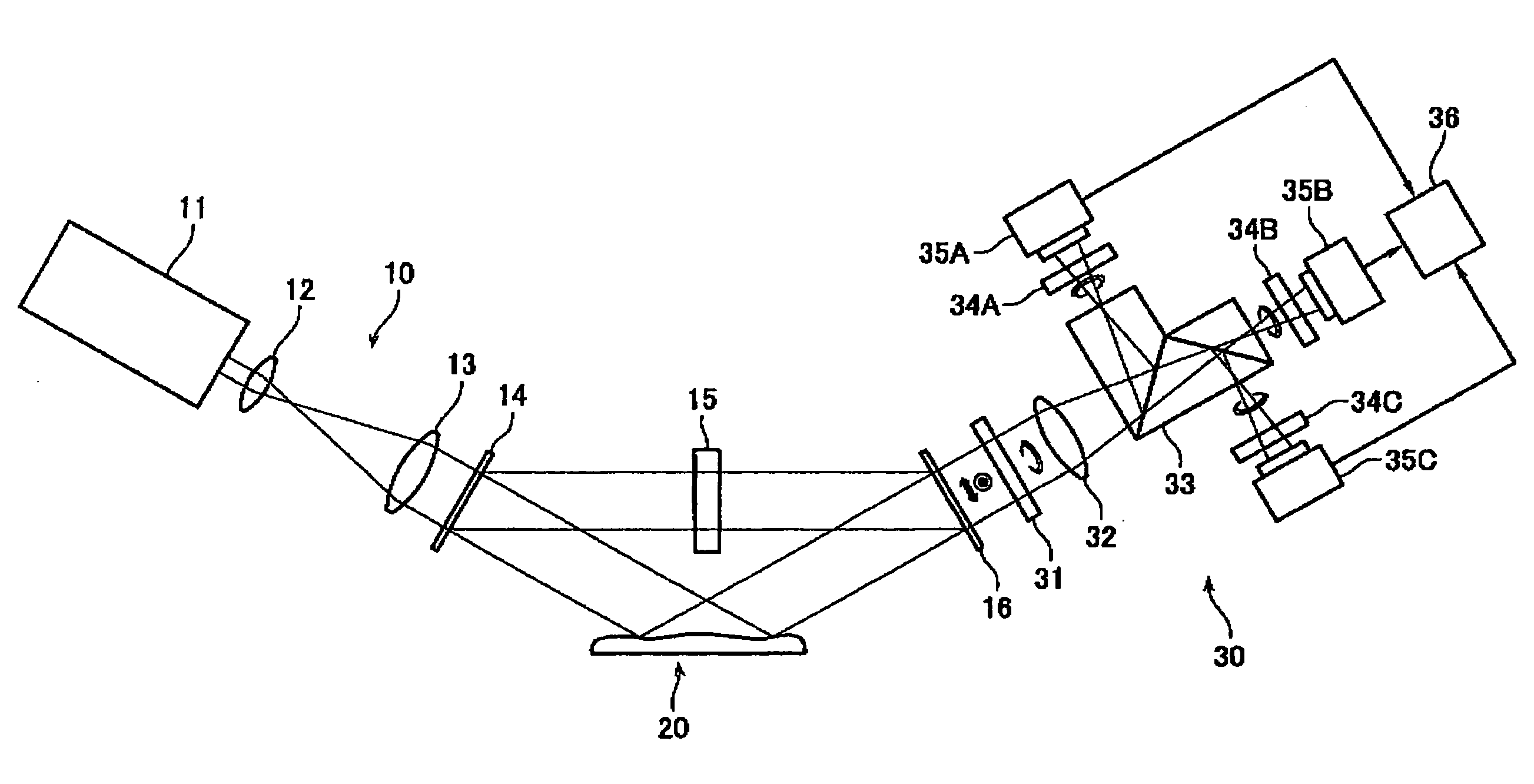
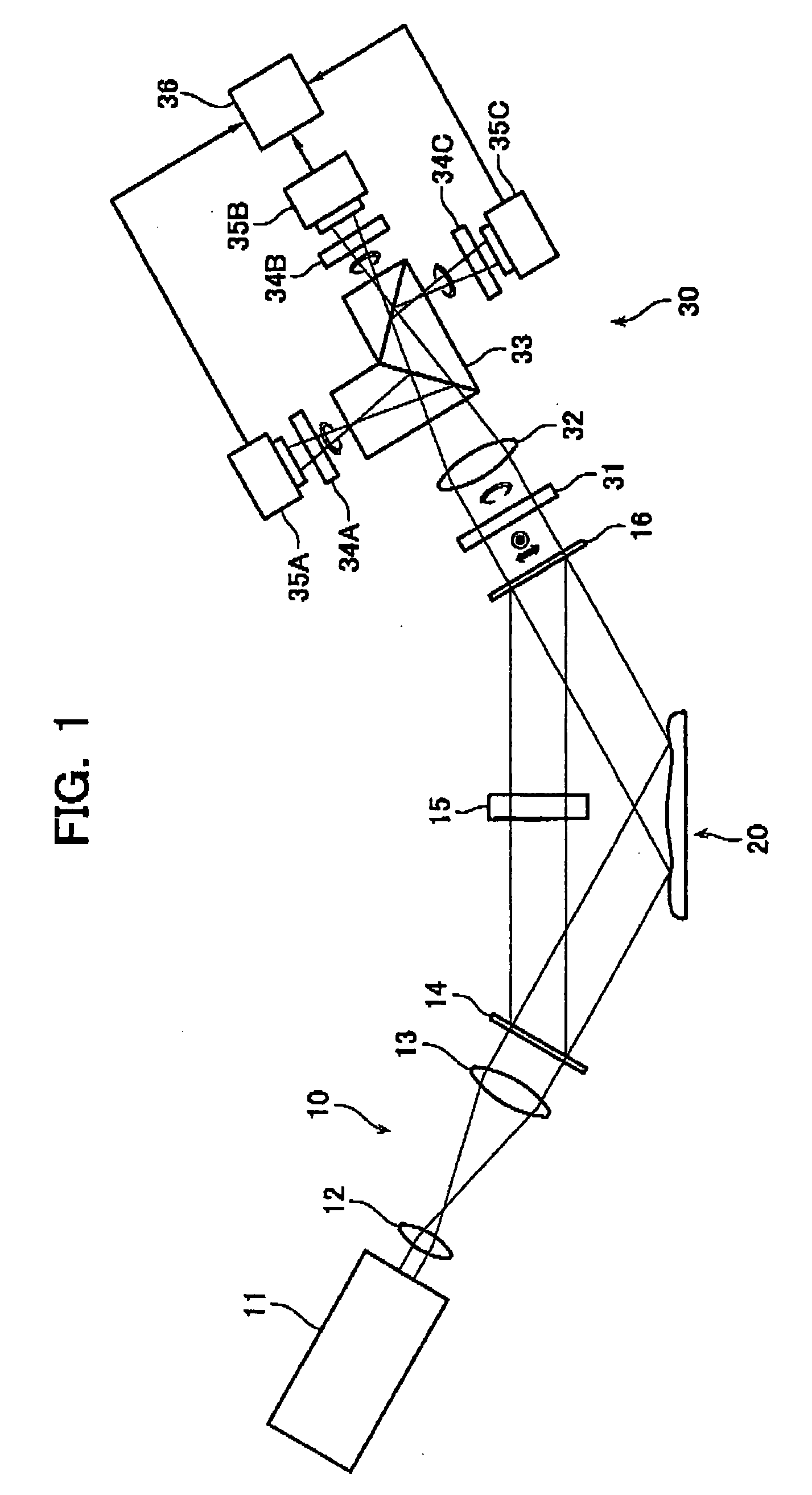
[0043]An oblique incidence interferometer according to a first embodiment of the present invention is described with reference to FIG. 1.
[0044]As shown in FIG. 1, the oblique incidence interferometer mainly comprises an illuminator unit 10, and a detector unit 30.
[0045]The illuminator unit 10 includes a light source 11, lenses 12, 13, a beam splitter element 14, a ½-waveplate 15, and a beam synthesizer element 16. In accordance with this arrangement, part of the light from the light source 11 is applied through the lenses 12, 13 and the beam splitter element 14 at a certain angle from the normal to a measurement surface of a target 20 to be measured. In the first embodiment, the light, which is applied to the target 20 through the beam splitter element 14 without changing direction, is used as a measurement light. In addition, the light, which is applied to the ½-waveplate 15 through the beam splitter element 14 with changing direction, is used as a reference light.
[0046]The detecto...
second embodiment
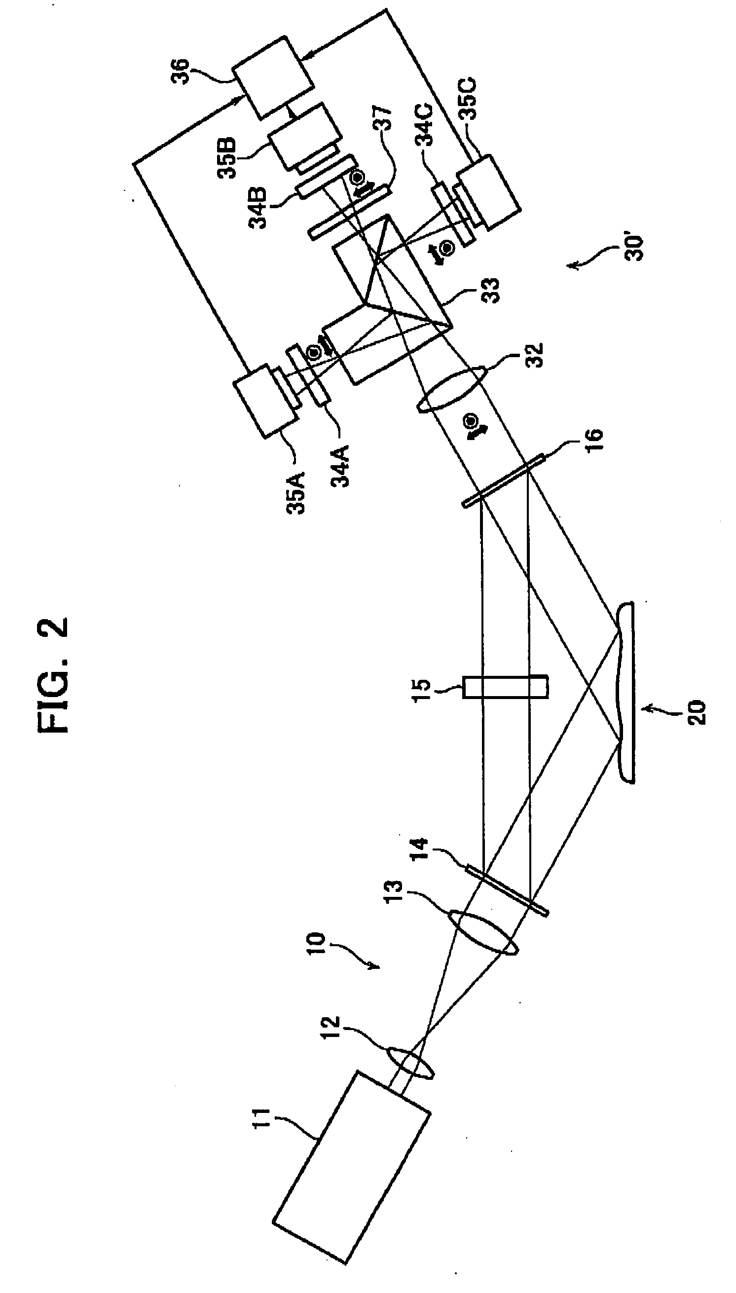
[0049]An oblique incidence interferometer according to a second embodiment of the present invention is described next with reference to FIG. 2, in which the same components as those in the above-described first embodiment are denoted with the same reference numerals and omitted from the following description. Also in the second embodiment, the light, which is applied to the target 20 through the beam splitter element 14 without changing direction, is used as a measurement light. In addition, the light, which is applied to the ½-waveplate 15 through the beam splitter element 14 with changing direction, is used as a reference light.
[0050]As shown in FIG. 2, the oblique incidence interferometer mainly comprises an illuminator unit 10, and a detector unit 30′. The illuminator unit 10 is similar to that in the first embodiment and the description thereof is omitted.
[0051]The detector unit 30′ includes a ¼-waveplate 37 newly arranged between the polarizer 34B and the three-way split prism...
third embodiment
[0055]An oblique incidence interferometer according to a third embodiment of the present invention is described next with reference to FIG. 3, in which the same components as those in the above-described first and second embodiments are denoted with the same reference numerals and omitted from the following description.
[0056]As shown in FIG. 3, the oblique incidence interferometer mainly comprises an illuminator unit 10′, and a detector unit 30. The detector unit 30 is similar to that in the first embodiment and the description thereof is omitted.
[0057]The illuminator unit 10′ includes a triangular prism 17, instead of the beam splitter element 14, the ½-waveplate 15 and the beam synthesizer element 16, different from the first embodiment.
[0058]When a beam is led into the triangular prism 17 at a certain particular angle, the relation between refractive indexes in the interior and exterior of the triangular prism 17 allows the beam of the parallel polarization to transmit, with resp...
PUM
 Abstract
Description
Claims
Application Information