
Apparatus for producing a label, apparatus for detecting a mark, apparatus for detecting a tape end, cartridge for producing a label roll of tape for producing a label, and marked tape

a technology for producing labels and markings, which is applied in the direction of typewriters, paper/cardboard articles, printing, etc. it can solve the problems of increasing manufacturing efforts and costs, detecting devices that cannot reliably recognize identification marks, and failure to prevent jamming, so as to prevent erroneous operations and/or inappropriate operations, the effect of preventing erroneous operations

Inactive Publication Date: 2008-01-03
BROTHER KOGYO KK
View PDF4 Cites 85 Cited by
  • Summary
  • Abstract
  • Description
  • Claims
  • Application Information

AI Technical Summary

Benefits of technology

The present invention provides a label producing apparatus that can prevent errors and inappropriate operations during the label production process. This includes detecting the mark on the tape and the tape end, preventing the tape from jamming in the label producing apparatus, and reliably recognizing the identification mark on the tape surface. Additionally, the invention can prevent errors in the detecting process by taking appropriate actions at the end of the tape or by sequentially and efficiently producing RFID labels while preventing errors in the cutting process.

Problems solved by technology

The web end detecting method and apparatus described in Patent Publication 1 do not particularly take into consideration such two tapes fed from respective rolls and therefore fails to prevent the jamming.
On the other hand, when a mark made of a different material is attached to the end of a tape as described in Patent Publication 2, extra steps are required for attaching such a mark on the tape, resulting in an increase in manufacturing efforts and cost.
Therefore, when the identification mark is relied on to conduct a variety of control operations for producing labels as described in Patent Publication 2, the detecting device will experience difficulties in distinguishing the identification mark from the decorative mark unless appropriate actions are taken therefor, and the detecting device can fail to reliably recognize the identification mark.
Consequently, the tape printing apparatus experiences difficulties in the print start timing control and tape cut positioning control based on the identification mark, and possibly suffers from a lower accuracy.
However, actually, the laminating apparatus avoids cutting the three-layer laminated portion in order to escape troubles in the motor due to the lack of its tape feeding capabilities, or tape jamming due to inappropriate pausing of the transport or cutting of the cutter resulting from the motor troubles.
In this event, if the cutter cuts part of an IC circuit part or an antenna of the RFID circuit element by mistake, the resulting RFID label can no longer serve as it should.
Patent Publication 3 does not disclose such cut position control for keeping normal the essential functions of a product itself.
As will be appreciated from the foregoing, the respective prior art techniques experience difficulties in preventing malfunctions and inappropriate operations, such as tape jamming (erroneous transport), failure in detection of a mark or tape end (erroneous detection), cutting of a RFID circuit element (erroneous cutting), during a sequence of label producing procedures of the label producing apparatus, which include operations for transporting tapes while detecting appropriate marks, performing predetermined processing such as printing, and cutting the tapes to form a label.

Method used


Image

  • Apparatus for producing a label, apparatus for detecting a mark, apparatus for detecting a tape end, cartridge for producing a label roll of tape for producing a label, and marked tape
  • Apparatus for producing a label, apparatus for detecting a mark, apparatus for detecting a tape end, cartridge for producing a label roll of tape for producing a label, and marked tape
  • Apparatus for producing a label, apparatus for detecting a mark, apparatus for detecting a tape end, cartridge for producing a label roll of tape for producing a label, and marked tape

Examples


first embodiment

[0120] the present invention will be described with reference to FIGS. 1 to 17.

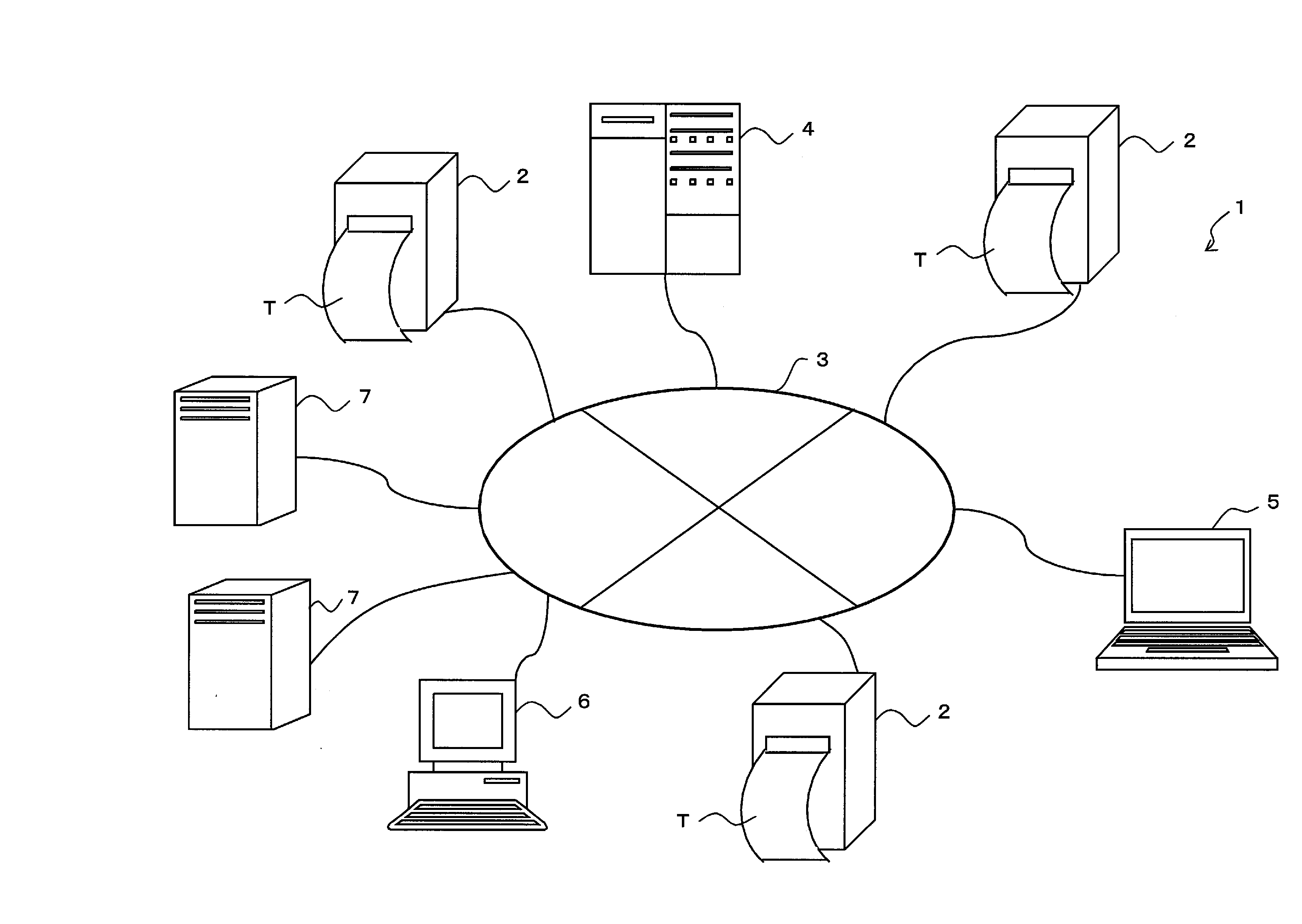
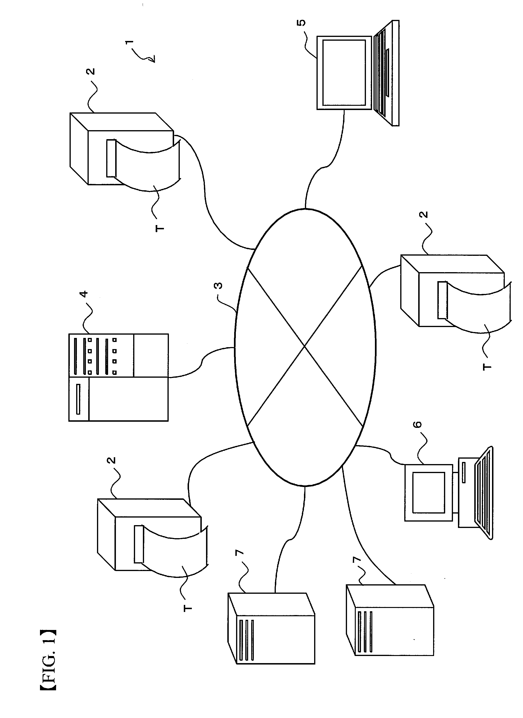
[0121]FIG. 1 is a diagram illustrating the configuration of a RFID tag manufacturing system to which a label producing apparatus is applied in accordance with the first embodiment.

[0122] In the RFID tag manufacturing system 1 illustrated in FIG. 1, the tag-label producing apparatus 2 (apparatus for producing a label) according to the embodiment is connected to a route server 4, a terminal 5, a general purpose computer 6, and a plurality of information servers 7 through a wired or a wireless communication network 3.

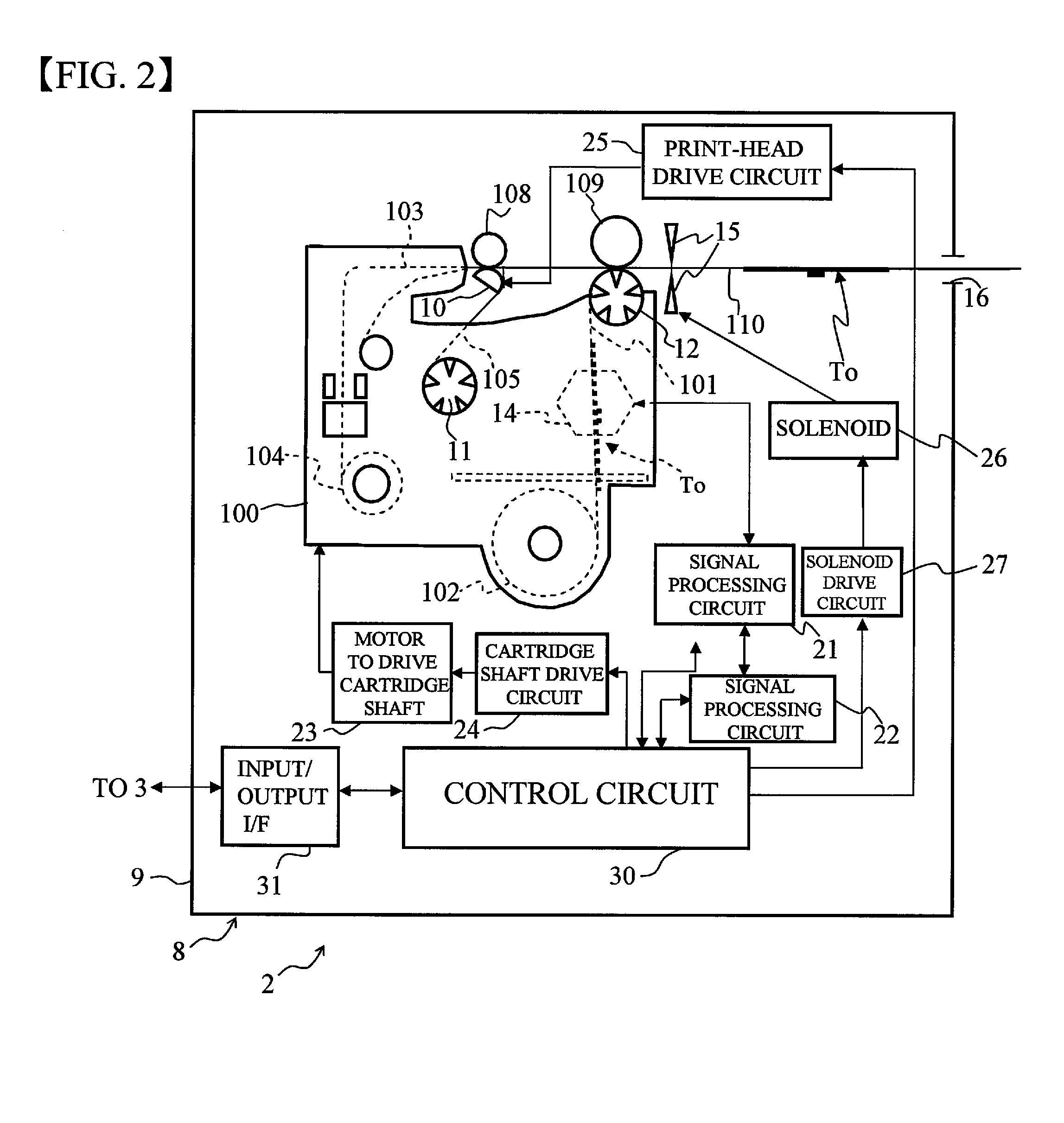
[0123]FIG. 2 is a conceptual diagram representing the configuration of the label producing apparatus 2 illustrated in FIG. 1 in greater detail.

[0124] In FIG. 2, a main body 8 of the label producing apparatus 2 is formed with a recessed cartridge holder (not shown, container receiving holder) in which a cartridge (label container) 100 is removably loaded.

[0125] The main body 8 comprises a pri...

third embodiment

[0226] the present invention will now be described with reference to FIGS. 21 to 38. The third embodiment relates to a label producing apparatus which comprises a malfunction preventing device that prevents malfunctions of a detecting device configured to detect an object to be detected on a label medium. Parts equivalent to those in the first and second embodiments are designated the same reference numerals, and descriptions thereon are omitted or simplified as appropriate.

[0227] The label producing apparatus 2 of the third embodiment is applied, for example, to the RFID tag manufacturing system 1 illustrated in FIG. 1 above, as is the case with the first and second embodiments described above. FIG. 21 is a diagram conceptually illustrating in detail the structure of the label producing apparatus 2, and is substantially comparable to FIG. 2 above.

[0228] Referring to FIG. 21, the tag-label producing apparatus 2 of the third embodiment differs from the tag-label producing apparatus ...


PUM


Abstract

An apparatus for producing a label prevents malfunctions and / or inappropriate operations possibly associated with respective processes in a label producing procedure. An adhesive layer of a base tape is wound around the peripheral surface of a first reel member to form a base tape roll. A print-receiving tape is wound around the peripheral surface of a second reel member to form a print-receiving tape roll. The two rolls are placed in a cartridge which is then loaded into the apparatus for producing a label. The base tape and print-receiving tape are fed out from the base tape roll and print-receiving tape roll, respectively, while a predetermined character is printed on the print-receiving tape. The printed print-receiving tape is bonded to the base tape to produce a RFID label. The first reel member associated with the base tape roll included in the cartridge is formed with a groove or a projection on the peripheral surface thereof.

Description

CROSS-REFERENCE TO RELATED APPLICATION [0001] This is a CIP application PCT / JP2005 / 023867, filed Dec. 27, 2005, which was not published under PCT article 21 (2) in English and claims the benefits of Japanese Patent application No. 2005-07361 filed Jan. 14, 2005, No. 2005-017492 filed Jan. 25, 2005, No. 2004-380321 filed Dec. 28, 2004, No. 2004-376906 filed Dec. 27, 2004, and No. 2005-117707 filed Apr. 15, 2005.BACKGROUND OF THE INVENTION [0002] 1. Field of the Invention [0003] The present invention relates to an apparatus for producing a label for sequentially producing labels, apparatus for detecting a mark configured to detect a mark and a tape end of a marked tape included in the apparatus for producing a label, and a cartridge for producing a label, a roll of tape for producing a label, and a marked tape for use in the apparatus for producing a label. [0004] 2. Description of the Related Art [0005] An apparatus for producing a label prints desired characters on a tape, i.e., a p...

Claims


Application Information

Patent Timeline
Patent Type & Authority Applications(United States)
IPC IPC(8): B41J11/00
CPCB31D1/021B31D1/027B41J3/4075B41J15/044B41J11/70B41J15/02B41J15/042B41J11/46
Inventor FUKUI, TOMOYASUNAGAI, TAKUYAMAEDA, YOSHINORITANAKA, MITSUGIMIYASHITA, HIROSHI
Owner BROTHER KOGYO KK
Learn More