Shape modification system for a cooling chamber of a medical device

a technology of cooling chamber and shape modification, which is applied in the direction of balloon catheters, catheters, surgery, etc., can solve the problems of limited use of catheters with balloons, the proportion of internal components of catheters to experience axial movement,

Active Publication Date: 2008-01-03
MEDTRONIC CRYOCATH LP
View PDF10 Cites 80 Cited by
  • Summary
  • Abstract
  • Description
  • Claims
  • Application Information

AI Technical Summary

Benefits of technology

[0007]The present invention advantageously provides a medical device in which an expandable element could be caused to deflate into its original, uninflated and folded orientation for ease of removal and/or repositioni...

Problems solved by technology

Such cycling can cause portions of the internal components of the catheter to experience axial movement.
Rather the balloon may bunch up or otherwise improperly deflate, causing the deflated balloon to have a larger than desirable radius, which may cause complications during the extraction and/or repositioning ...

Method used


Image

  • Shape modification system for a cooling chamber of a medical device
  • Shape modification system for a cooling chamber of a medical device
  • Shape modification system for a cooling chamber of a medical device

Examples


Embodiment Construction

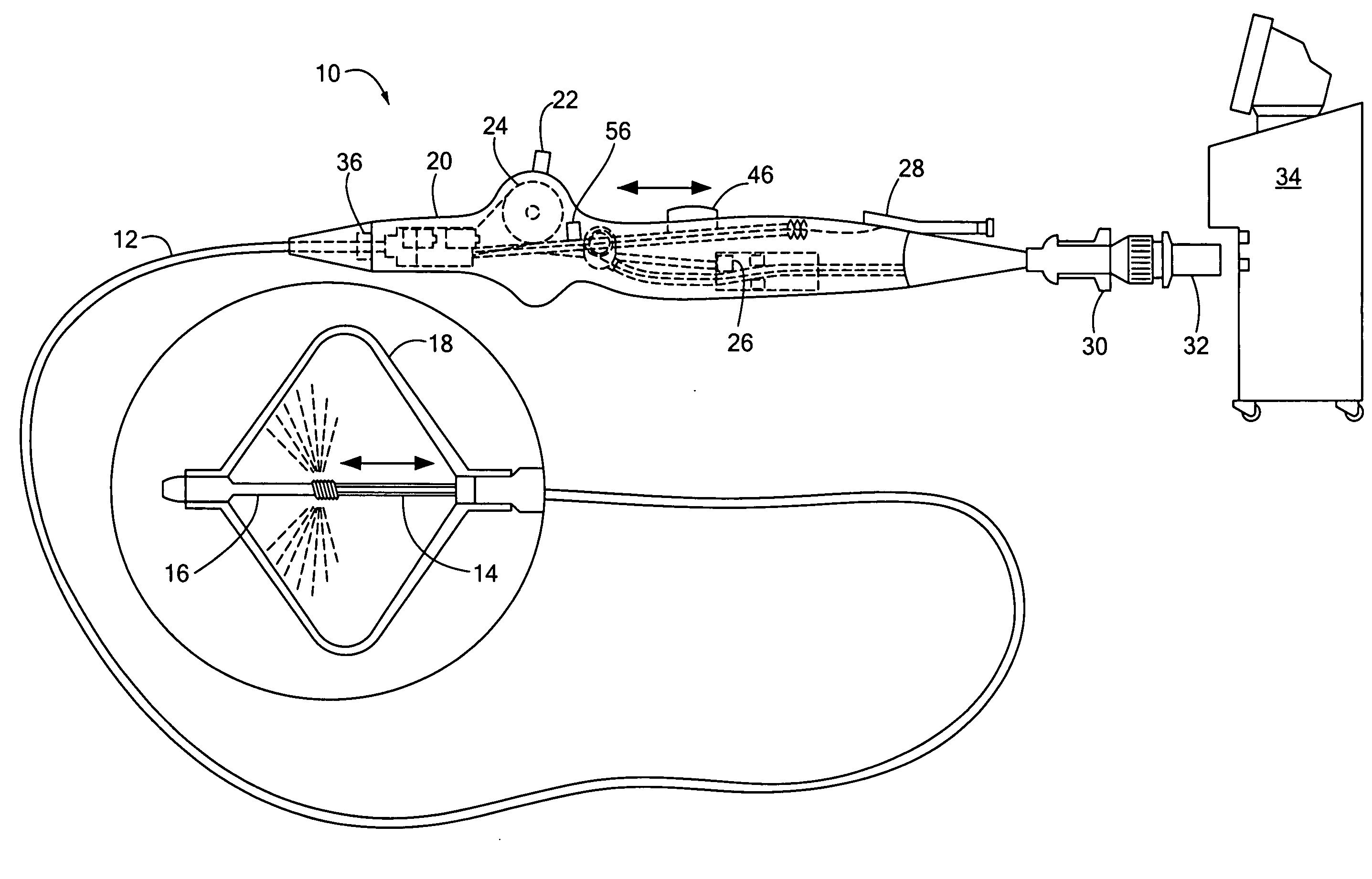
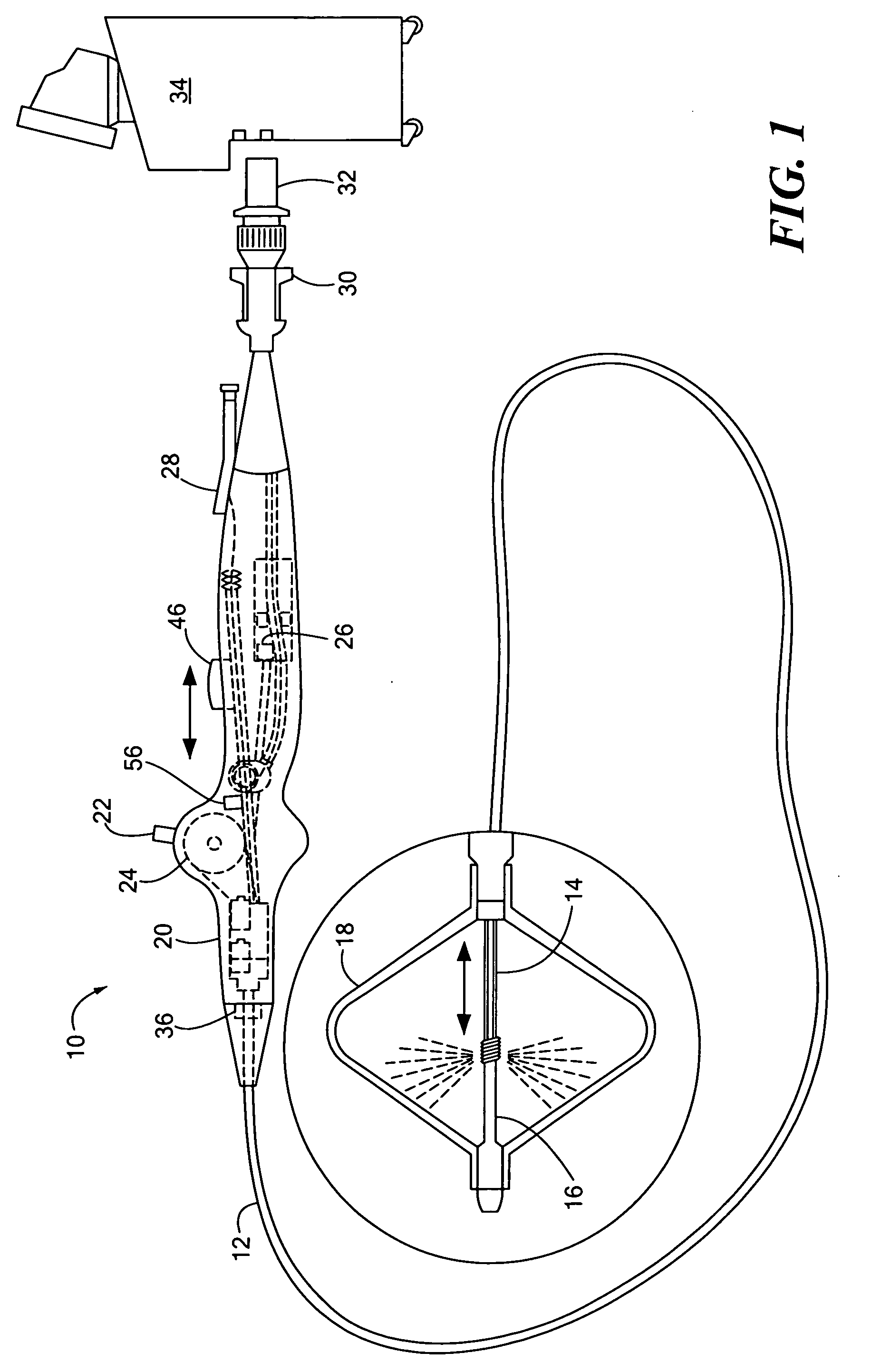
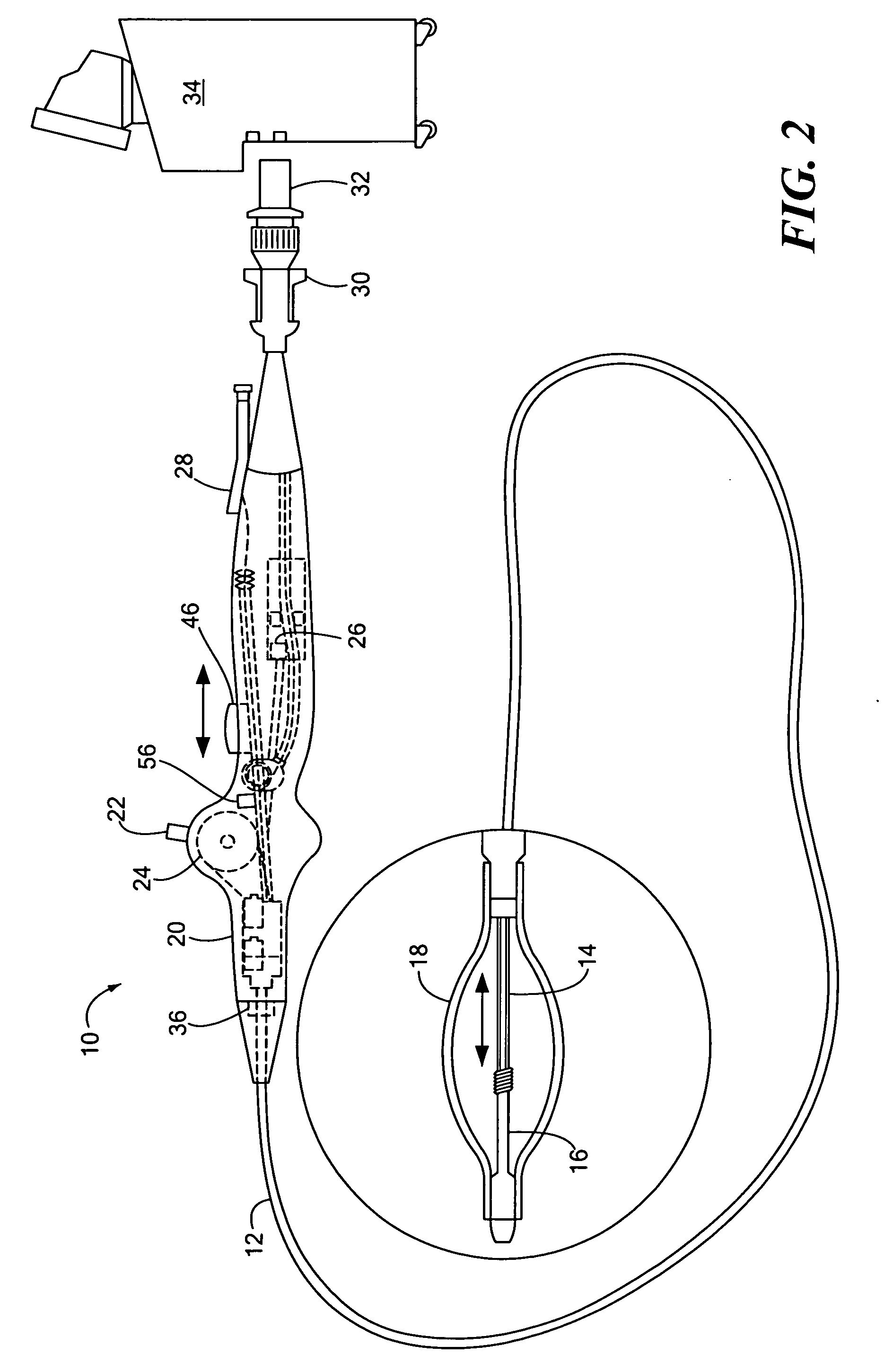
[0019]Now referring to FIGS. 1 and 2, an embodiment of the present invention provides a medical device, generally designated as 10. The medical device 10 may include an elongate body 12, such as a catheter. The elongate body 12 may define a proximal portion and a distal portion, and may further include one or more lumens may disposed within the elongate body 12 thereby providing mechanical, electrical, and / or fluid communication between the proximal portion of the elongate body 12 and the distal portion of the elongate body 12. For example, the elongate body 12 may include an injection lumen 14 and an exhaust lumen defining a fluid flow path therethrough. In addition, the elongate body 12 may include a guidewire lumen 16 movably disposed within and / or extending along at least a portion of the length of the elongate body 12 for over-the-wire applications. The guidewire lumen 16 may define a proximal end and a distal end, and the guidewire lumen 16 may be movably disposed within the e...


PUM


Abstract

The present invention provides a medical device having an catheter body defining proximal and distal portions, and a guidewire lumen at least partially disposed within and movable within the catheter body. The medical device may include an expandable element defining a proximal end and a distal end, wherein the proximal end is coupled to the distal portion of the catheter body and the distal end is coupled to the guidewire lumen. In addition, an actuator element may be coupled to the guidewire lumen for longitudinal movement thereof, and a tensioning element may further be coupled to the guidewire lumen to bias the guidewire lumen and/or the expandable element towards a particular geometric configuration.

Description

CROSS-REFERENCE TO RELATED APPLICATION[0001]n / aSTATEMENT REGARDING FEDERALLY SPONSORED RESEARCH OR DEVELOPMENT[0002]n / aFIELD OF THE INVENTION[0003]The present invention relates to a method and system for modifying and controlling forces applied to a portion of a medical device, and more particularly, to a method and system for tensioning and / or varying the shape of an expandable element.BACKGROUND OF THE INVENTION[0004]Numerous procedures involving catheters and other minimally invasive devices may be performed to provide a wide variety of treatments, such as ablation, angioplasty, dilation or the like. Prior to insertion into a vessel and / or placement near a particular tissue region, the balloon is typically in a deflated state, and may include a number of folds that reduce the cross-sectional area of the balloon to ease insertion and / or placement. During a particular procedure, the balloon may be transitioned between inflated and deflated states in order to provide the desired aff...

Claims


Application Information

Patent Timeline
IPC IPC(8): A61M29/00A61F2/958
CPCA61M2025/1068A61M25/1018A61B2018/0212A61M25/10181
Inventor ABBOUD, MARWANWITTENBERGER, DAN
Owner MEDTRONIC CRYOCATH LP
Why Eureka
Try Eureka