Control device of a storage system comprising storage devices of a plurality of types

a storage system and control device technology, applied in the direction of electric digital data processing, instruments, computing, etc., can solve the problems of flash memory being written, the life of flash memory eventually drops, and the bit cost of flash memory is higher than the bit cost of a hard disk

Inactive Publication Date: 2008-01-03
HITACHI LTD
View PDF1 Cites 45 Cited by
  • Summary
  • Abstract
  • Description
  • Claims
  • Application Information

AI Technical Summary

Benefits of technology

[0015]The control device according to the present invention is a control device of a storage system that comprises a plurality of each of storage devices of a plurality of types comprising storage devices of a first and second type. The control device comprises a first acquisition module for acquiring an archive deadline of archive target data which are the target of archiving by the storage system; a second acquisition module for acquiring a warranty deadline for the quality of data stored by the storage device and unit costs constituting the costs for a predetermined storage size of the storage device for each of the storage devices of the plurality of types; a third acquisition module for acquiring data migration costs constituting the costs required for data migration from a certain storage device among the storage devices of the plurality of types to another storage device among the storage devices of the plurality of types; and a selection module for selecting a storage device constituting the storage destination of the archive target data from the storage devices of the plurality of types on the basis of the archive deadline, warranty deadline, unit cost and data migration cost thus acquired. The selected storage device is a storage device of a type for which the total cost when the archive target data are archived until the warranty deadline is minimum. The total cost is a cost that is obtained from a first cost obtained from the product of the number of data migrations and the data migration cost, a unit cost of a data migration source, and a unit cost of a data migration destination.
[0016]The control device may be a host computer of a storage system (a host computer that issues an IO command to the storage system or a management computer that manages the storage system, for example), and may be provided in a storage system or may be provided in an intermediate device that is provided between the storage system and the host computer. Alternatively, the respective parts of the control device may be provided distributed between at least two of the host device of the storage system, the intermediate device and the storage system.

Problems solved by technology

However, the bit costs of flash memory are, at the time this specification was written, higher than the bit costs of a hard disk.
When the technology of Japanese Patent Application Laid Open No. 2005-301684 is simply applied to such a storage system, the following problems can arise.
However, because of the restrictions on the write number, there are cases where the lifespan of the flash memory eventually drops as the write number of the data of the flash memory increases.
Further, as mentioned earlier, the bit costs when data are stored are generally higher for flash memory than for a hard disk.
In addition, bit costs are also incurred when data migration is performed from a certain storage device to another storage device.
Hence, when data archiving is performed without considering the number of data migrations or the data archiving location and so forth, there is a risk of high costs being incurred in the data archiving.
The above problem can arise only when the storage devices of the plurality of types are a hard disk and flash memory.

Method used


Image

  • Control device of a storage system comprising storage devices of a plurality of types
  • Control device of a storage system comprising storage devices of a plurality of types
  • Control device of a storage system comprising storage devices of a plurality of types

Examples


first embodiment

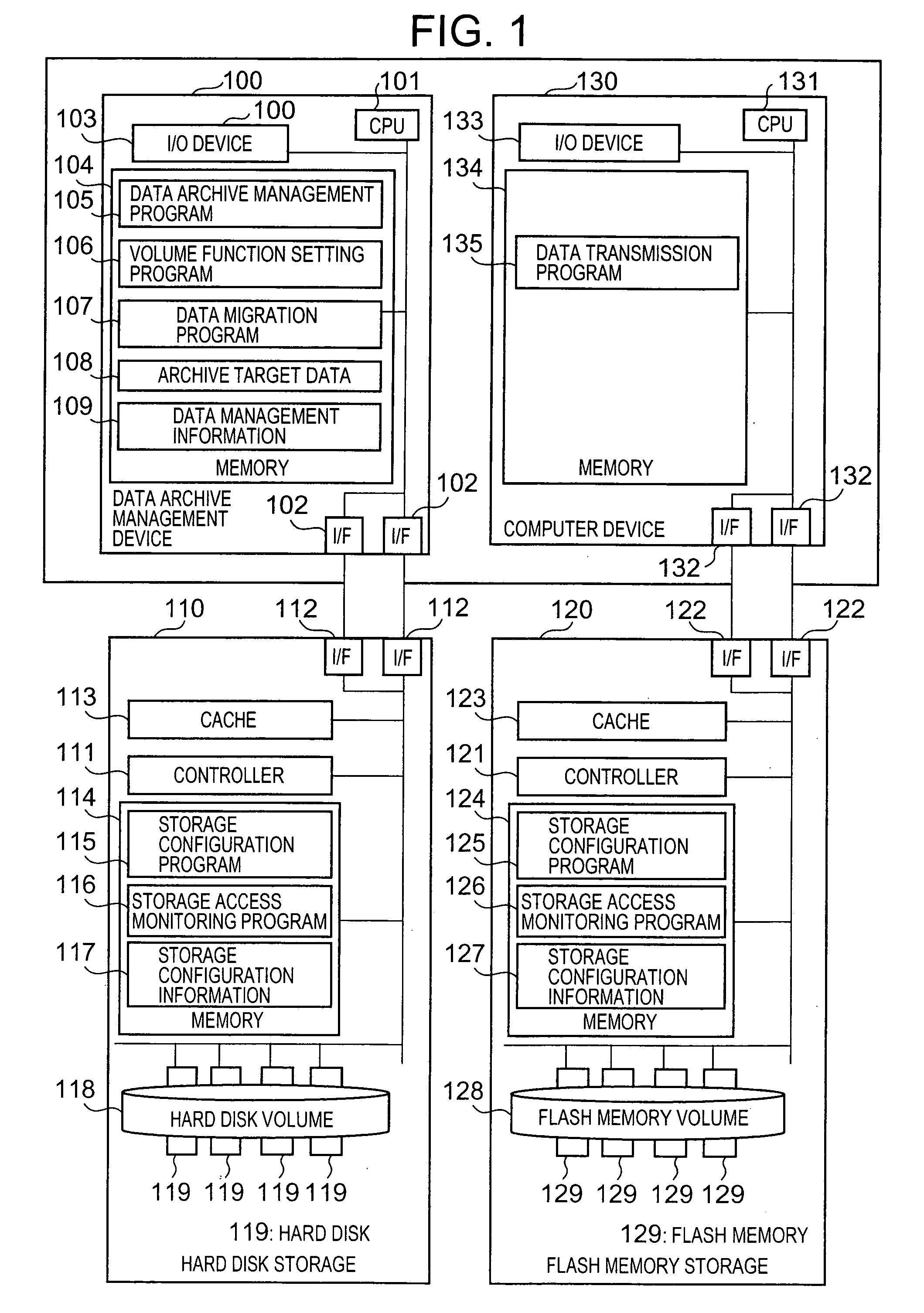
[0042]FIG. 1 shows a constitutional example of a computer system according to a first embodiment of the present invention.

[0043]A data archive management device 100, a computer device 130, the hard disk storage 110, and flash memory storage 120 are connected to a communication network.

[0044]The data archive management device 100 is a computer comprising a CPU 101, a communication interface device (‘I / F’ hereinbelow) 102, an I / O device 103, and a memory 104.

[0045]The I / F 102 communicates with the hard disk storage 110, flash memory storage 120, and the computer device 130.

[0046]A plurality of computer programs executed by a CPU 101 and data referenced by the CPU 101 are stored in the memory 104. More specifically, for example, a data archive management program 105, a volume function setting program 106, a data migration program 107, archive target data 108, and data management information 109 are stored. The archive target data 108 and data management information 109 are information ...

second embodiment

[0133]The second embodiment of the present invention will be described hereinbelow. Further, differences from the first embodiment will mainly be described below and descriptions of points in common with the first embodiment will be omitted or simplified (the same is true of the other embodiments).

[0134]FIG. 7 shows a constitutional example of the data management information 109 of the second embodiment of the present invention.

[0135]In the second embodiment, the configuration of the archive data management information table 400 differs from that of the first embodiment. Hence, FIG. 7 shows the archive data management information table 400. Because there is no difference in the configuration of the cost table 410 and write threshold value table 420, tables 410 and 420 are not shown in FIG. 7. Further, because a data characteristic table 710 is added in the second embodiment, FIG. 7 shows the constitutional example of the table 710.

[0136]In addition to the columns described in the fi...

third embodiment

[0164]FIG. 11 shows a constitutional example of the data management information 109 of the third embodiment of the present invention.

[0165]In the third embodiment, in addition to the elements described in the second embodiment, a volume function table 1100 and a volume function correspondence table 1110 are also included in the data management information 109.

[0166]The volume function table 1100 has a column 1101 in which the volume function (in other words, the application) is written, a column 1102 in which the access pattern of the volume function is written, and a column 1103 in which the Read / Write focus of the volume function is written.

[0167]Here, volume functions include, for example, a snapshot pool that indicates a volume group for storing a snapshot differential, a journal pool constituting a volume group for managing information corresponding with the volume update history and the data update order and so forth, and a dynamic volume expansion pool constituting a volume g...


PUM


Abstract

The control device acquires the archive deadline of archive target data and acquires, for storage devices of a plurality of types, a warranty deadline for the quality of data stored by the storage device and the unit cost which is the cost for each predetermined storage size of the storage device. The storage control device is a storage device which acquires a data migration cost and which obtains a storage destination for the archive target data from storage devices of a plurality of types on the basis of the archive deadline, warranty deadline, unit cost and data migration cost thus acquired. The storage control device selects a storage device for which the total cost is minimum when the archive target data is archived until the archive deadline.

Description

CROSS-REFERENCE TO PRIOR APPLICATION[0001]This application relates to and claims priority from Japanese Patent Application No. 2006-183710, filed on Jul. 3, 2006 the entire disclosure of which is incorporated herein by reference.BACKGROUND OF THE INVENTION[0002]1. Field of the Invention[0003]The present invention relates to control of a storage system that comprises storage devices of a plurality of types.[0004]2. Description of the Related Art[0005]The storage system can be constituted by one or a plurality of storage subsystems (sometimes called simply ‘storage’ hereinbelow). A plurality of storage devices can be installed in the storage.[0006]In a computer system in an enterprise or the like, the storage capacity of the storage also increases as the amount of data stored by the storage increases and as data is held for long periods. Further, in order to hold data for long periods, data must be archived by considering the warranty periods of the respective storage devices in the s...

Claims


Application Information

Patent Timeline
Patent Type & Authority Applications(United States)
IPC IPC(8): G06F12/16
CPCG06F3/0605G06F3/0647G06F17/30551G06F3/0688G06F3/0689G06F3/0649G06F16/2477
Inventor ASANO, MASAYASUYAMAMOTO, MASAYUKITAGUCHI, YUICHIKIHARA, KENICHI
Owner HITACHI LTD
Why Eureka
Try Eureka