Dehumidifier and centrifugal blower thereof

a centrifugal blower and dehumidifier technology, which is applied in the direction of heating types, separation processes, domestic cooling apparatus, etc., can solve the problems of flow noise and decrease in blowing efficiency, and achieve the effect of improving the blowing efficiency of centrifugal blowers and reducing nois

Inactive Publication Date: 2008-01-10
SAMSUNG ELECTRONICS CO LTD
View PDF13 Cites 18 Cited by
  • Summary
  • Abstract
  • Description
  • Claims
  • Application Information

AI Technical Summary

Benefits of technology

[0009]The present general inventive concept provides a dehumidifier wherein the structure of a centrifugal blower is modified to improve the blowing efficiency of the centrifugal blower and to reduce noise.

Problems solved by technology

As a result, flow resistance is greatly generated in the dehumidifier, and therefore, the blowing efficiency is decreased, and flow noise is generated.

Method used


Image

  • Dehumidifier and centrifugal blower thereof
  • Dehumidifier and centrifugal blower thereof
  • Dehumidifier and centrifugal blower thereof

Examples


Embodiment Construction

[0034]Reference will now be made in detail to the embodiments of the present general inventive concept, examples of which are illustrated in the accompanying drawings, wherein like reference numerals refer to the like elements throughout. The embodiments are described below in order to explain the present general inventive concept by referring to the figures.

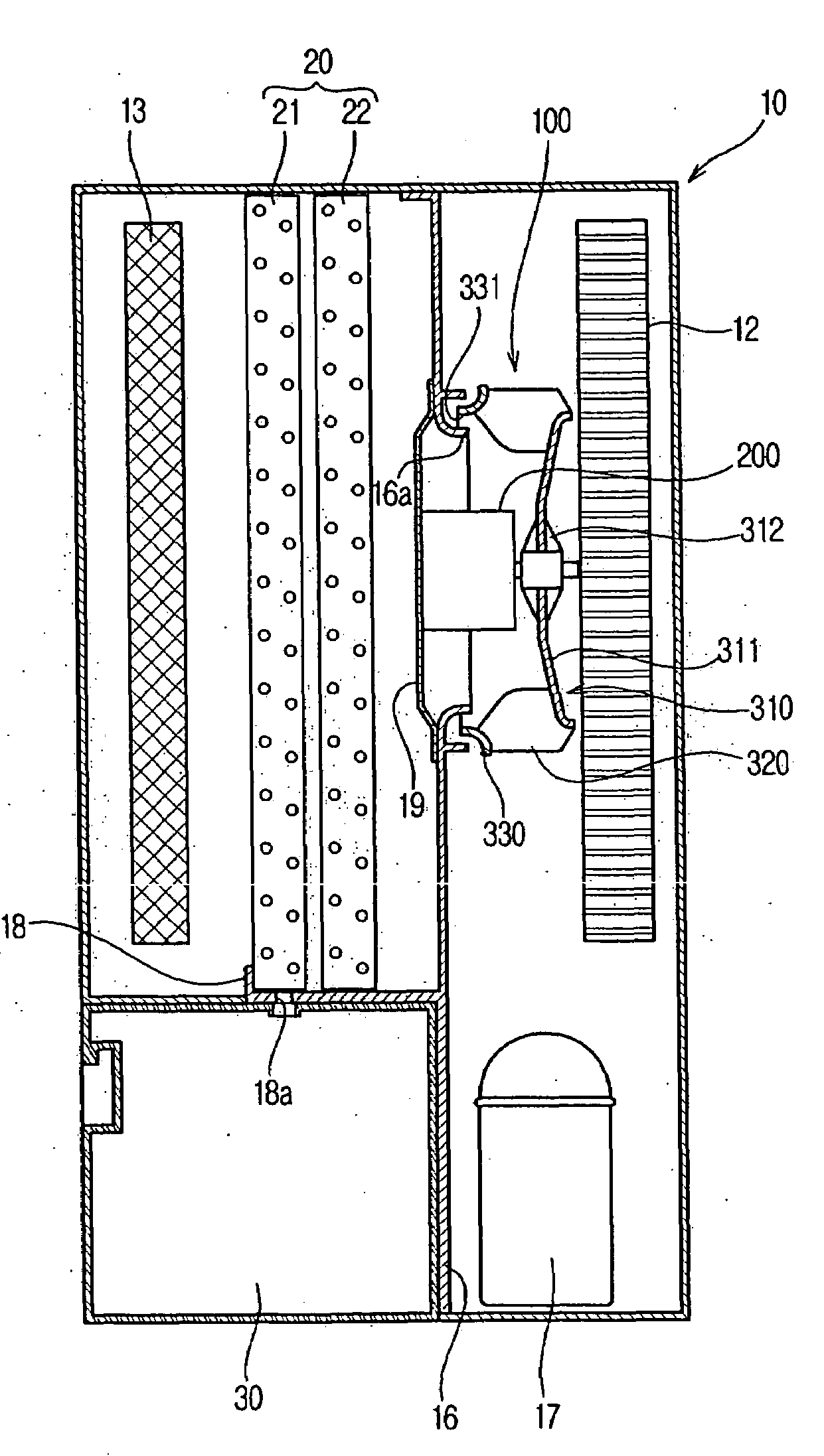
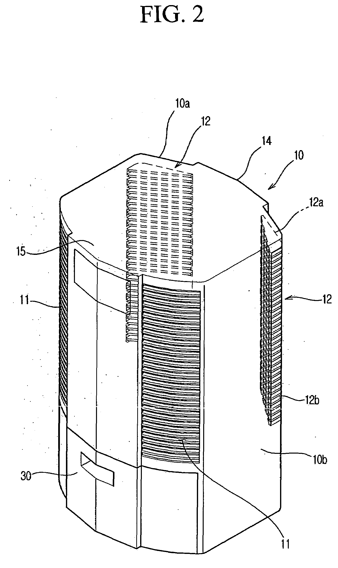
[0035]FIG. 2 is a perspective view illustrating the external appearance of a dehumidifier according to an embodiment of the present general inventive concept, FIG. 3 is a side view illustrating the structure of the dehumidifier according to an embodiment of the present general inventive concept, and FIG. 4 is a perspective view illustrating a centrifugal fan of the dehumidifier according to an embodiment of the present general inventive concept.

[0036]As illustrated in FIGS. 2 and 3, the dehumidifier includes a body 10 having inlet ports 11, through which room air is introduced, and outlet ports 12, through which the air is disch...


PUM


Abstract

A dehumidifier includes a body having inlet and outlet ports and a centrifugal fan mounted inside the body to circulate air. The centrifugal fan includes a fan disk coupled to a fan motor such that the fan disk can be rotated, and the fan disk includes an incline inclined toward the outlet ports to guide the flow of air passing through the centrifugal fan to the outlet ports. The incline extends from a motor coupling part of the fan disk, which is coupled to the fan motor, in the radial direction. Blades are mounted at the outer circumference of the incline.

Description

CROSS-REFERENCE TO RELATED APPLICATIONS[0001]This application claims priority under 35 U.S.C. §119(a) from Korean Patent Application No. 2006-64546, filed on Jul. 10, 2006 in the Korean Intellectual Property Office, the entire disclosure of which is incorporated herein by reference.BACKGROUND OF THE INVENTION[0002]1. Field of the Invention[0003]The present general inventive concept relates to a dehumidifier having a centrifugal blower, and, more particularly, to a dehumidifier wherein the structure of a centrifugal blower is modified to improve the blowing efficiency of the centrifugal blower.[0004]2. Description of the Related Art[0005]A dehumidifier is an apparatus that removes moisture from air using movement of heat generated during condensation. The dehumidifier includes a blowing fan to circulate room air. When a turbo fan is used as the blowing fan to blow a desired amount of air, noise is reduced as compared to when an axial fan is used as the blowing fan.[0006]An example of...

Claims


Application Information

Patent Timeline
Patent Type & Authority Applications(United States)
IPC IPC(8): F25D17/06F25D21/00B01D53/26F04D25/06F04D29/28F04D29/30F04D29/44F04D29/70
CPCF04D17/06F04D29/281F24F13/24F04D29/663F24F3/153F04D29/5826F04D29/28F24F3/12F24F3/14
Inventor KIM, JIN BAEKMO, JIN YONGKIM, YOUNG JAELEE, JAI KWON
Owner SAMSUNG ELECTRONICS CO LTD
Why Eureka
Try Eureka