Circuit for safe forwarding of an analog signal value

a technology of analog electrical signal and safe forwarding, which is applied in the direction of programme control, emergency protective arrangements for limiting excess voltage/current, instruments, etc., can solve the problem of increasing the demands for functional safety that cannot be met, and achieve the effect of increasing the functional safety of the transmitter and high probability

Active Publication Date: 2008-01-10
BERTHOLD TECH
View PDF2 Cites 34 Cited by
  • Summary
  • Abstract
  • Description
  • Claims
  • Application Information

AI Technical Summary

Benefits of technology

[0016] It is the object of the present invention to increase the functional safety of a transmitter or evaluation system in a circuit of the generic type here to at least Stage SIL 2, by assuring that the current flowing in the current loop, which is

Problems solved by technology

A disadvantage of this embodiment, however, is considered to be that the measurement resistor provided there is not itself monitored for fault, so that a fau

Method used


Image

  • Circuit for safe forwarding of an analog signal value
  • Circuit for safe forwarding of an analog signal value
  • Circuit for safe forwarding of an analog signal value

Examples


Embodiment Construction

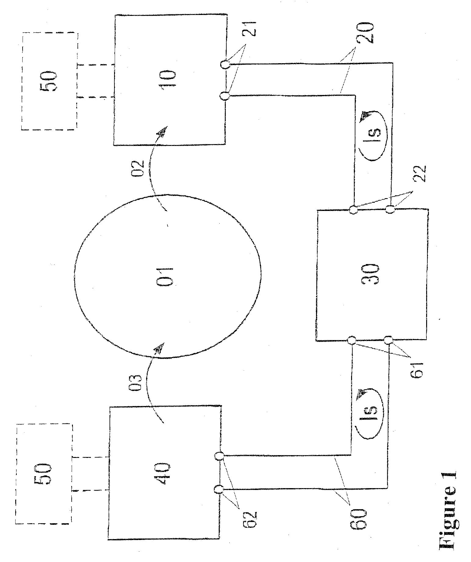
[0032]FIG. 1, first, shows a typical example of use in processing control technology, in which physical and technical variables are transmitted between various systems by means of analog electrical signals. In this example, for regulating a technical process 01 (such as a chemical reaction in a reactor), the control system 30 must at all times know the value of a physical variable 02 (such as fill level, temperature, pressure, etc.) of the process 01 and keep it within predetermined limits. To that end, the physical variable 02 is detected by a transmitter 10 and converted into an analog electrical signal, which is made available as a loop current signal Is to the current loop 20 via the terminals 21 and is acquired by the control system 30 via the terminals 22. The transmitter may additionally be supplied with auxiliary energy via an external current supply 50.

[0033] Via a different current signal Is, which the control system 30 makes available to a further current loop 60 via the...


PUM


Abstract

In a circuit for safe forwarding of a physical or technical variable between at least two systems in communication with one another, which variable is represented by the value of a loop current (Is), which is adjusted by a control unit (11) by means of a current output circuit (13) in a current loop (20, 60), the current output circuit (13) has at least two parallel-connected final control elements (131, 132), controllable by the control circuit (11), as current sources for mutually independent adjustment of a value of the loop current (Is). The final control elements (131, 132) are in series with at least two likewise series-connected measurement resistors (133a, 133b). The voltage, proportional to the loop current (Is), dropping via at least one but not all of the at least two measurement resistors is fed back to the control unit (11), which compares the value of this voltage with the corresponding value of the loop current, which value is specified to at least one of the final control elements, and in the event of deviations, via a predeterminable threshold, allocates an fault value corresponding to the NAMUR recommendation NE043 to the loop current via the first final control element (131), and in the case of failure of the first final control element (131) via the second final control element (132). A monitoring circuit (17) is provided, which in the event of failure of the control unit (11) allocates an fault value that likewise corresponds to the NAMUR recommendation NE043 to the loop current via the second final control element (132). The invention, compared to embodiments based on the principle of redundance, thus makes it possible to disclose a more-favorable embodiment for monitoring and signalling faults, which makes do with only one current path. The circuit may be designed in that way. By additional wiring, the demands in terms of explosion protection by intrinsic safety, functional safety (up to at least SIL 2), HART communication, and a standardized interface in accordance with NAMUR recommendation NE43 with an upper fault current (greater than 21 mA) and a lower fault current (less than 3.6 mA) and an active mode (current source) and passive mode (current sink) can be met at the same time.

Description

BACKGROUND OF THE INVENTION [0001] The invention relates to an electronic circuit for safe forwarding of an analog electrical signal value (hereinafter called simply signal for short) between two or more systems communicating with one another. The signal may for instance be the representation of a physical variable (such as pressure, temperature, brightness, conductivity, etc.) or a technical variable (such as fill level, flow rate, set-point or actual values of a controlling value or closed control loop, etc.). The conversion of the physical or technical variable (hereinafter called variable for short) into a signal representing it is done by sensor or detector systems (hereinafter called transmitters for short) on-site, at the place (“in the field”) where the variable is to be detected or ascertained (the terms field devices or field transmitters are therefore often also used). The signal thus ascertained is then made available for further processing to other systems, sometimes ev...

Claims


Application Information

Patent Timeline
IPC IPC(8): H03B19/00
CPCG05B2219/25428G05B19/0425
Inventor FREIBURGER, EWALDBRIGGMANN, JURGEN
Owner BERTHOLD TECH
Why Eureka
Try Eureka