Liquid crystal display device and driving method of liquid crystal display device

a technology of liquid crystal display and driving method, which is applied in the direction of instruments, static indicating devices, etc., can solve the problems of not achieving sufficient dark-place contrast and sufficient moving image characteristics in some use of display, and achieve the effect of improving moving image characteristics and improving contras

Active Publication Date: 2008-01-10
SATURN LICENSING LLC
View PDF8 Cites 26 Cited by
  • Summary
  • Abstract
  • Description
  • Claims
  • Application Information

AI Technical Summary

Benefits of technology

[0020]In the liquid crystal display device having the above-described constitution, the first liquid crystal panel is driven by n-time speed driving and the second liquid crystal panel is driven by normal driving, or the first liquid crystal panel and the second liquid crystal panel are both driven by the n-time speed driving. Thereby the display of the display device as a whole is an impulse type display in which pixels blink, which is a factor in improving moving image characteristics.
[0021]According to the present invention, it is possible to provide a liquid crystal display device and a driving method of the liquid crystal display device that use the technique for dramatically improving contrast by laminating a plurality of liquid crystal panels and which can achieve moving image characteristics (response characteristics) comparable to those of the CRT.

Problems solved by technology

It is known, however, that even combinations of the techniques such as the overdrive technique, the scan backlight technique, black insertion, and n-time speed driving cannot achieve sufficient dark-place contrast and sufficient moving image characteristics in some uses of the display.

Method used


Image

  • Liquid crystal display device and driving method of liquid crystal display device
  • Liquid crystal display device and driving method of liquid crystal display device
  • Liquid crystal display device and driving method of liquid crystal display device

Examples


embodiments

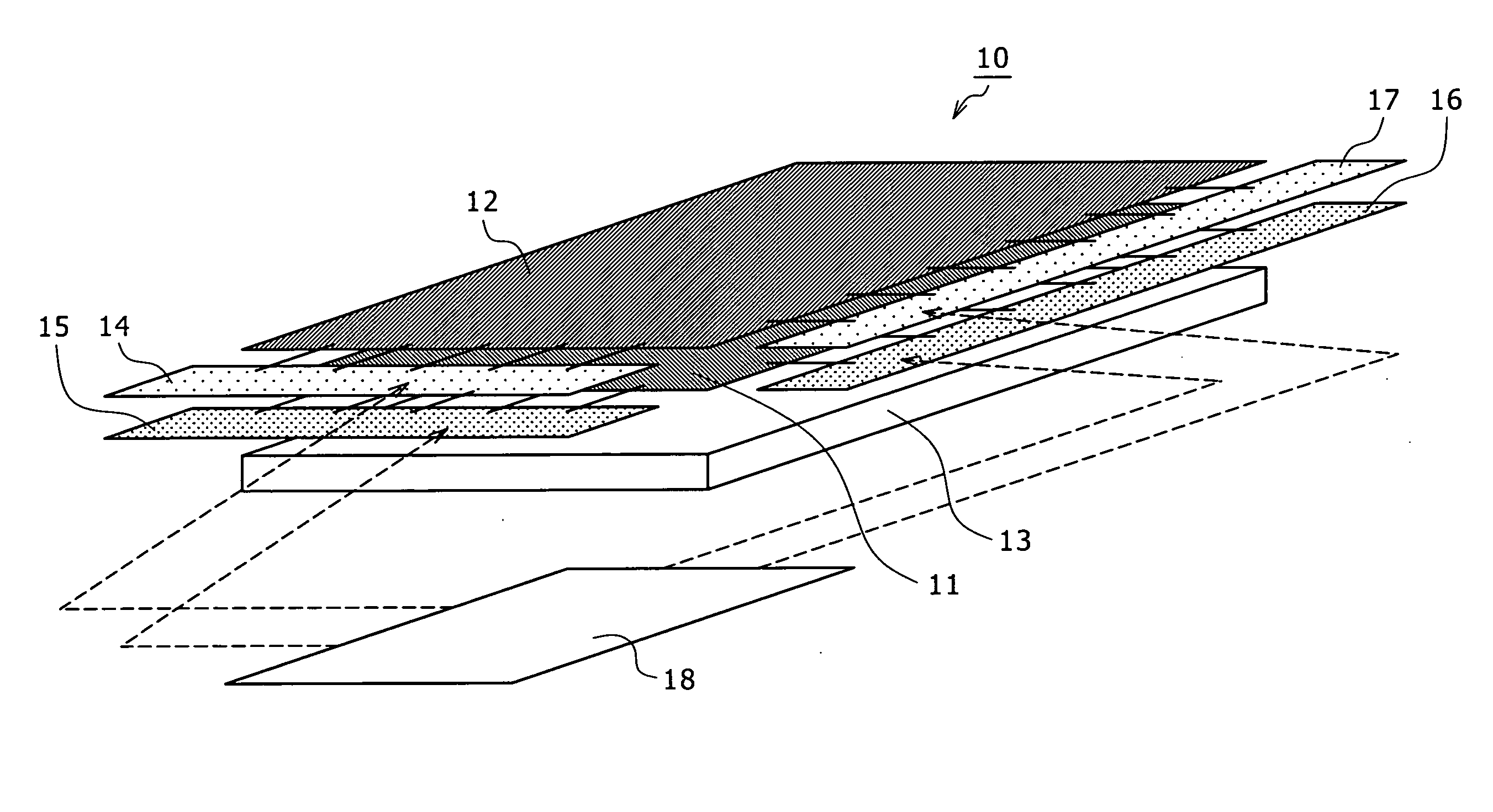
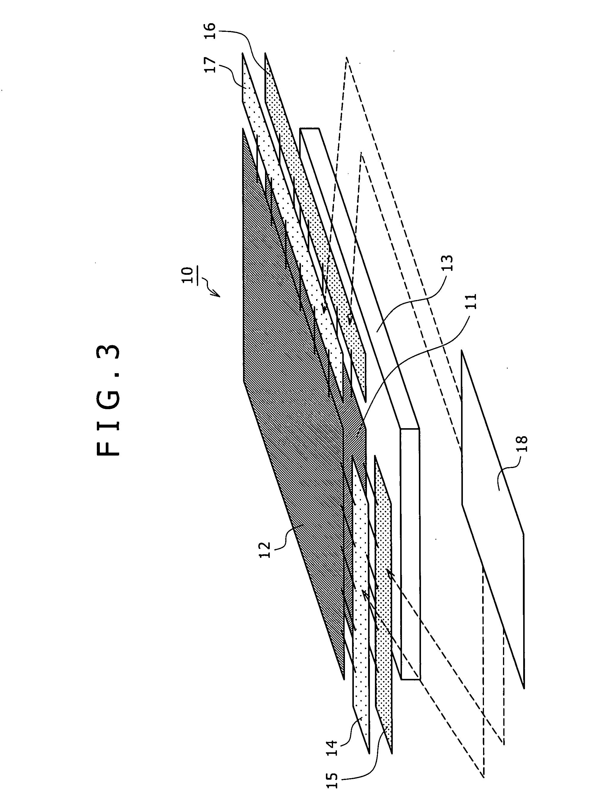
[0045]FIG. 3 is a conceptual diagram schematically showing a system configuration of a liquid crystal display device according to an embodiment of the present invention. As shown in FIG. 3, the liquid crystal display device 10 according to the present embodiment has a structure in which a plurality of liquid crystal panels, for example two first and second liquid crystal panels 11 and 12 are laminated in order from the bottom of FIG. 3 such that optical axes of pixels of the liquid crystal panels 11 and 12 coincide with each other, a backlight unit 13 is disposed on the side of the first liquid crystal panel 11 on the lower side, and light emitted from the backlight unit 13 is transmitted in order by the pixels of the first and second liquid crystal panels 11 and 12 according to transmittance of the pixels.

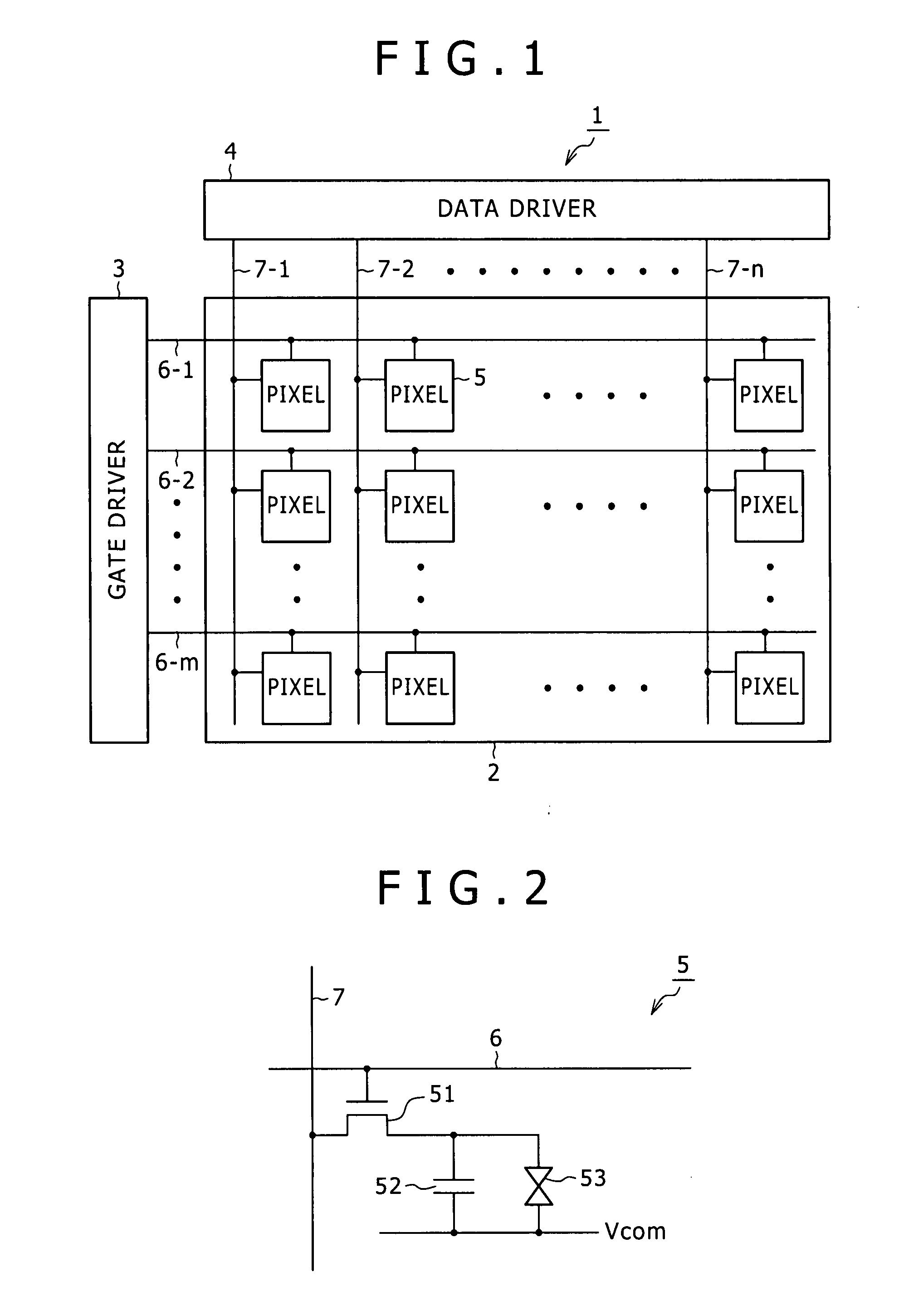
[0046]The first and second liquid crystal panels 11 and 12 have basically the same structure. Specifically, as shown in FIG. 1, the first and second liquid crystal panels 11 and 1...

first embodiment

[0056]A liquid crystal display device according to a first embodiment performs normal driving of a second liquid crystal panel 12 and performs double-speed driving of a first liquid crystal panel 11 under driving by a driving circuit 8. In this case, normal driving refers to driving at a frequency (driving frequency) of an input signal (video signal), that is, driving in which one frame period is not divided. Hence, double-speed driving refers to driving at a frequency twice the frequency of the input video signal.

[0057]In the liquid crystal display device that thus performs the double-speed driving of the first liquid crystal panel 11 and the normal driving of the second liquid crystal panel 12, when the response waveform of the second liquid crystal panel 12 is a waveform as shown in FIG. 5A in which a transient change is made from a black gradation to a predetermined gradation (for example a gradation of 200) in the period of one frame, and the first liquid crystal panel 11 is dr...

second embodiment

[0068]Supposing the normal driving of a second liquid crystal panel 12 and the double-speed driving of a first liquid crystal panel 11 under driving by a driving circuit 8, a liquid crystal display device according to a second embodiment changes repetitive gradations of the first liquid crystal panel 11, or specifically changes gradations in a first field and a second field, according to display of the second liquid crystal panel 12.

[0069]In the liquid crystal display device according to the first embodiment, the first liquid crystal panel 11 repeats the same gradations irrespective of input level of the second liquid crystal panel 12. In this case, a leakage of light occurs when the second liquid crystal panel 12 has the gradation voltage of black. This cancels out the effect of enhancing the ability to represent black by laminating the two liquid crystal panels 11 and 12.

[0070]On the other hand, the liquid crystal display device according to the second embodiment changes repetitiv...


PUM


Abstract

Disclosed herein is a liquid crystal display device formed by laminating at least two first and second liquid crystal panels, the liquid crystal panels being each formed by disposing a liquid crystal layer between two transparent substrates arranged so as to be opposed to each other and two-dimensionally arranging pixels in a form of a matrix on one of the two substrates, and disposing a backlight on a side of the first liquid crystal panel. The liquid crystal display device includes: a first driver configured to drive the first liquid crystal panel on a side of the backlight by n-time speed driving in which one frame period is divided into n fields; and a second driver configured to drive the second liquid crystal panel on a display surface side by normal driving in which one frame period is not divided.

Description

CROSS REFERENCES TO RELATED APPLICATIONS[0001]The present invention contains subject matter related to Japanese Patent Application JP 2006-187401, filed in the Japan Patent Office on Jul. 7, 2006, the entire contents of which being incorporated herein by reference.BACKGROUND OF THE INVENTION[0002]1. Field of the Invention[0003]The present invention relates to a liquid crystal display device and a driving method of the liquid crystal display device, and particularly to an active matrix type liquid crystal display device that controls display in pixel units, and a driving method of the liquid crystal display device.[0004]2. Description of the Related Art[0005]The liquid crystal display device is now widely used in portable terminals, PC (personal computer) monitors, devices for commercial use, and digital TVs because of reduced thickness, light weight, and low power consumption of the liquid crystal display device. For TV use, in particular, the liquid crystal display device is compar...

Claims


Application Information

Patent Timeline
Patent Type & Authority Applications(United States)
IPC IPC(8): G09G3/36
CPCG09G3/2025G09G3/3406G09G3/3614G09G3/3648G09G2300/023G09G2310/0237G09G2340/0435G09G2320/0252G09G2320/0261G09G2320/0276G09G2320/041G09G2320/066G09G2320/10G09G2310/061
Inventor TANAKA, RYO
Owner SATURN LICENSING LLC
Why Eureka
Try Eureka