Vehicle wheel alignment system scanned beam imaging sensor

a beam imaging and vehicle wheel technology, applied in the field of imaging sensors, can solve the problems of not being adopted for vehicle service applications, standard area imaging sensors suffer from a number of restrictions, and standard area imaging sensors are susceptible to specular reflection problems

Inactive Publication Date: 2008-01-10
HUNTER ENG
View PDF31 Cites 48 Cited by
  • Summary
  • Abstract
  • Description
  • Claims
  • Application Information

AI Technical Summary

Problems solved by technology

Standard area imaging sensors suffer from a number of restrictions when utilized in an automotive service environment.
Additionally, standard area imaging sensors are susceptible to specular reflection problems, such as may arise when bright lights are reflected from shiny or chromed surfaces of a vehicle or vehicle wheel rim.
Confocal imaging has found application in specialized medical, scientific, or industrial imaging where a combination of high magnification and high resolution are desired, but has not been adopted for use in vehicle service applications.
Even with the trend to incorporate more pixels on conventional image sensors, this trade off makes some aspects of machine vision wheel alignment system designs impractical.
With conventional image sensors, the focusing optics impose physical design limits which restricts possible configurations of vision-based aligners.
These systems generally employ rotating mirrors to steer the illuminating light or laser beam, and are not well suited for use in automotive aligner applications because they are relatively expensive, delicate, and require significant maintenance.

Method used


Image

  • Vehicle wheel alignment system scanned beam imaging sensor
  • Vehicle wheel alignment system scanned beam imaging sensor
  • Vehicle wheel alignment system scanned beam imaging sensor

Examples


Embodiment Construction

[0038] The following detailed description illustrates the invention by way of example and not by way of limitation. The description clearly enables one skilled in the art to make and use the invention, describes several embodiments, adaptations, variations, alternatives, and uses of the invention, including what is presently believed to be the best mode of carrying out the invention.

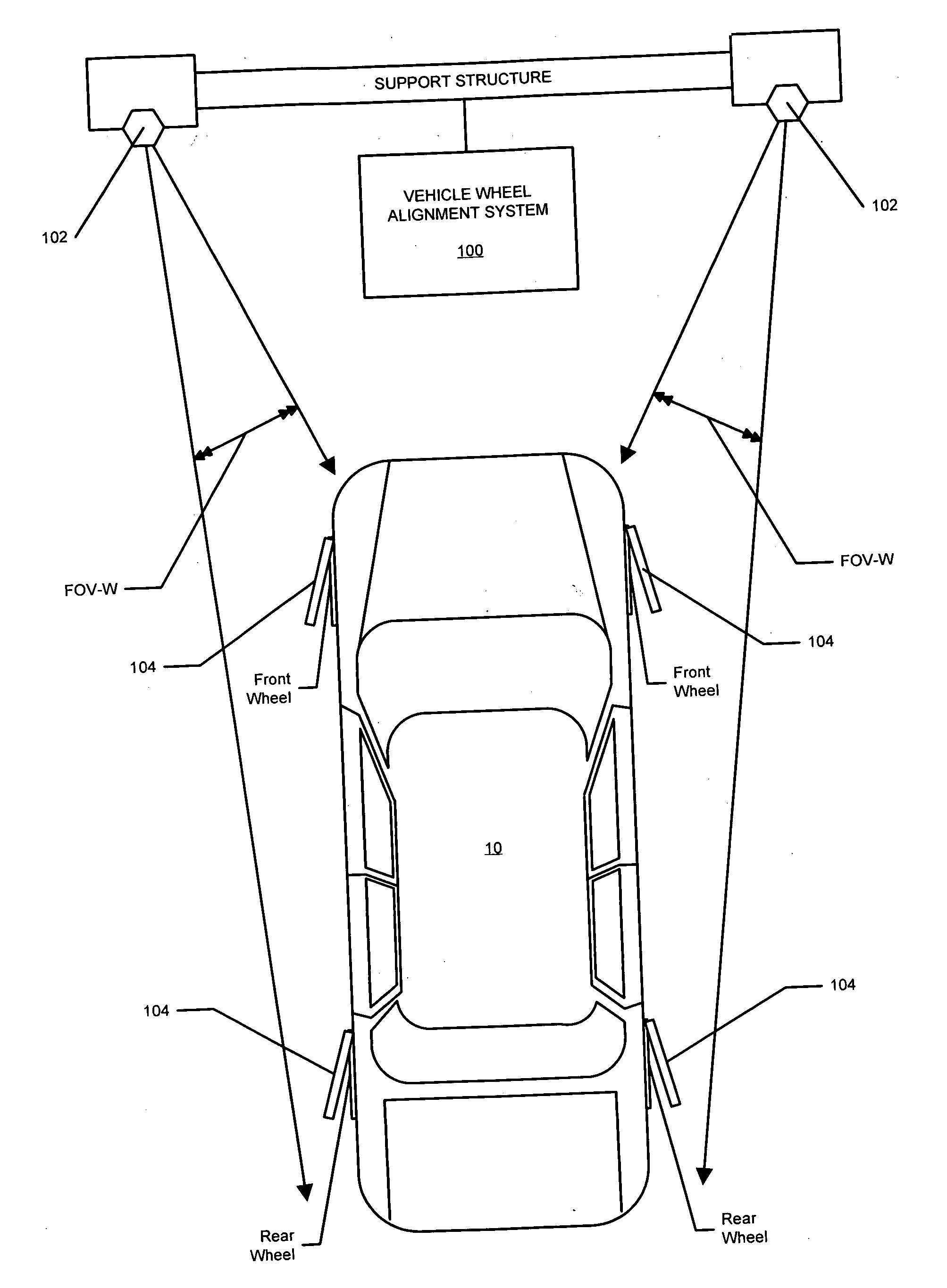
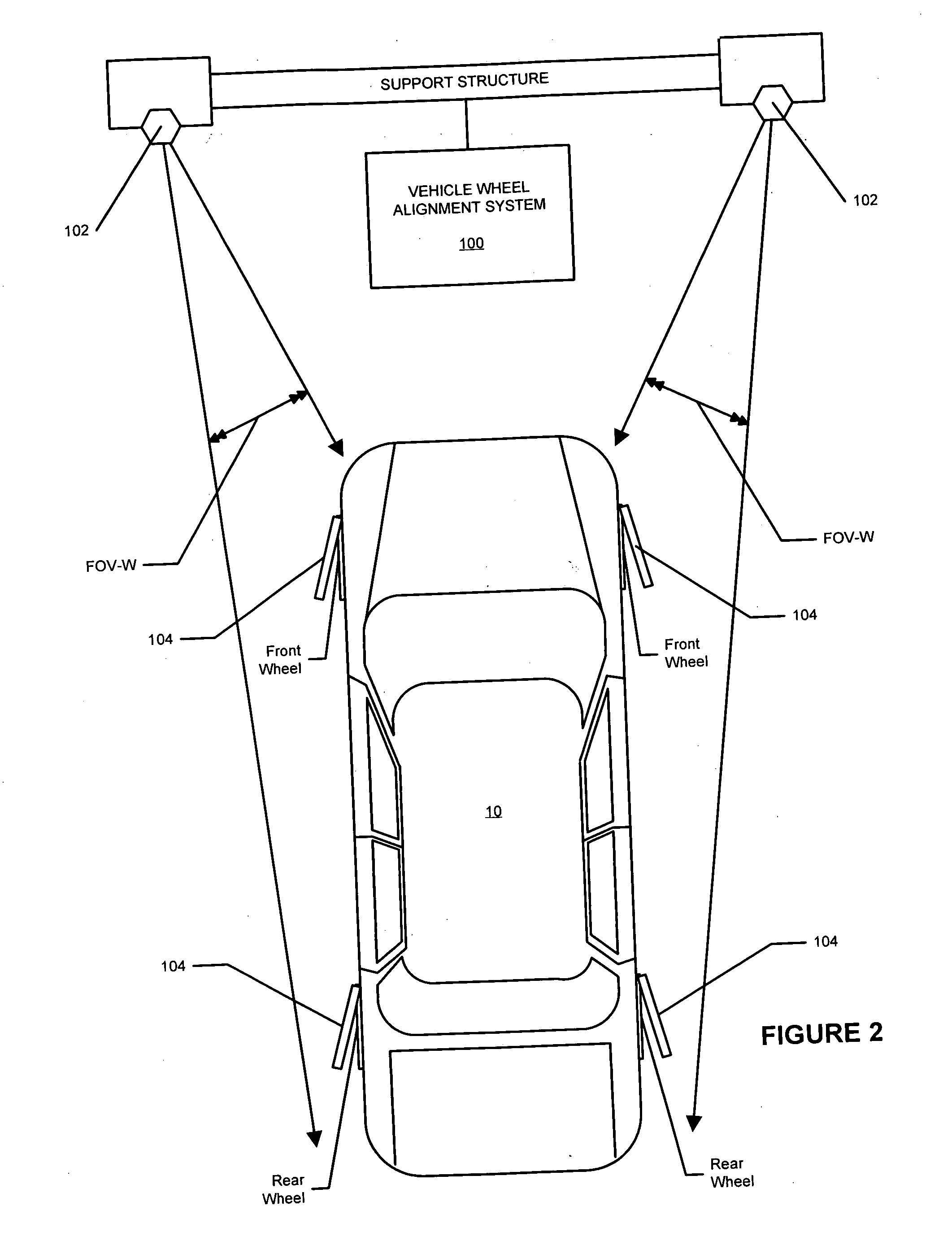
[0039] Machine vision vehicle wheel alignment systems such as shown in U.S. Pat. No. 6,298,284 B1 to Burns, Jr. et al., herein incorporated by reference, typically utilize a set of solid state cameras having traditional area imaging sensors, mounted away from a vehicle undergoing an alignment inspection, to obtain images of wheel-mounted alignment targets. As is conventional in the field of machine vision vehicle wheel alignment systems, the alignment targets incorporate accurately reproduced patterns and / or known control features, as set forth in U.S. Pat. No. 6,064,750 to January et al., herein incorp...


PUM


Abstract

A vehicle wheel alignment sensor for a machine-vision vehicle wheel alignment system comprising a scanned beam camera incorporating an illumination source, a means for deflecting light emitted by the illumination source along a path within a field of view, and a detector array for receiving illumination reflected from objects within the field of view to generate an image which is representative of a region of interest within the field of view.

Description

CROSS-REFERENCE TO RELATED APPLICATIONS [0001] The present application is related to, and claims priority from, U.S. Provisional Patent Application No. 60 / 664,748 filed on Mar. 24, 2005, which is herein incorporated by reference.STATEMENT REGARDING FEDERALLY SPONSORED RESEARCH [0002] Not Applicable. BACKGROUND OF THE INVENTION [0003] The present invention relates to imaging sensors utilized in conjunction with a vehicle wheel alignment system to acquire data with are either representative of vehicle wheel alignment angles, or from which vehicle wheel alignment angles can be calculated, and in particular, to an improved machine vision vehicle wheel alignment sensor incorporating a scanned beam imaging system to generate an image associated with a vehicle wheel from which alignment angle information can be determined. [0004] Aligning vehicle wheels within specific tolerances is important for optimal control of the vehicle and for consistent wear of the tires. Alignment is performed pr...

Claims


Application Information

Patent Timeline
Patent Type & Authority Applications(United States)
IPC IPC(8): G01C1/00
CPCG01B11/2545G01B11/2755G01C11/025G01B2210/28G01B2210/286G01B2210/143
Inventor GOLAB, THOMAS J.DORRANCE, DANIEL R.
Owner HUNTER ENG
Why Eureka
Try Eureka