Eureka AIR delivers breakthrough ideas for toughest innovation challenges, trusted by R&D personnel around the world.

Connector and method of connecting the same

a technology of connecting connectors and connectors, which is applied in the direction of coupling contact members, coupling device connection, engagement/disengagement of coupling parts, etc., can solve the problems of conventional connectors having a reliability problem, conventional connectors having a problem of more than downsizing, and preventing the damage of contacts, so as to improve the assurance and reliability, prevent mechanical stress, and prevent the effect of contact damag

Inactive Publication Date: 2008-01-10
VISTA PEAK VENTURES LLC
View PDF2 Cites 0 Cited by
  • Summary
  • Abstract
  • Description
  • Claims
  • Application Information

AI Technical Summary

Benefits of technology

[0010]In view of the foregoing and other exemplary problems, drawbacks, and disadvantages of the related art methods and structures, exemplary feature of the present invention is to provide a connector and a method of connecting the connector, with which it is possible to prevent mechanical stress from being generated between contacts when a plug is inserted into a socket.
[0014]Accordingly, the connector and the method of connecting the connector according to the present invention provide the following effects by employing the above described configurations and method. More specifically, it is possible to prevent mechanical stress from being generated between contacts when a plug is inserted into a socket, and thus to prevent a contact from being damaged. As a result, the connector and the method of connecting the connector according to the present invention further provide an effect in which it is possible to improve assurance and reliability at the time of connection.

Problems solved by technology

Moreover, the contacts 104, if not deformed, may possibly be damaged.
For this reason, a conventional connector has a problem of reliability at the time of connection.
However, in recent years, a connector mounted on a printed wiring board has been downsized more than ever as an electronic circuit on the printed wiring board has been miniaturized.
As a result, the contacts may possibly be deformed or damaged.
As a result, a problem may occur in which electrical connection loss is increased due to an increase in contact resistance.
Accordingly, a problem may occur in which electrical losses in the connection is increased due to increase in contact resistance.
As described above, the aforementioned connectors have problems in assurance and reliability at the time of connection.

Method used


Image

  • Connector and method of connecting the same
  • Connector and method of connecting the same
  • Connector and method of connecting the same

Examples


Embodiment Construction

[0024]Preferred embodiments for carrying out the present invention will be described in detail below with reference to the drawings. The preferred embodiments described below show only illustrative examples in understanding the present invention, and the claims of the invention are not limited to these preferred embodiments.

[0025]Descriptions of a preferred embodiment of a connector and a method of connecting the connector according to the present invention will be given below.

[0026]Firstly, descriptions of a configuration of a connector according to an embodiment of the present invention will be given in detail below.

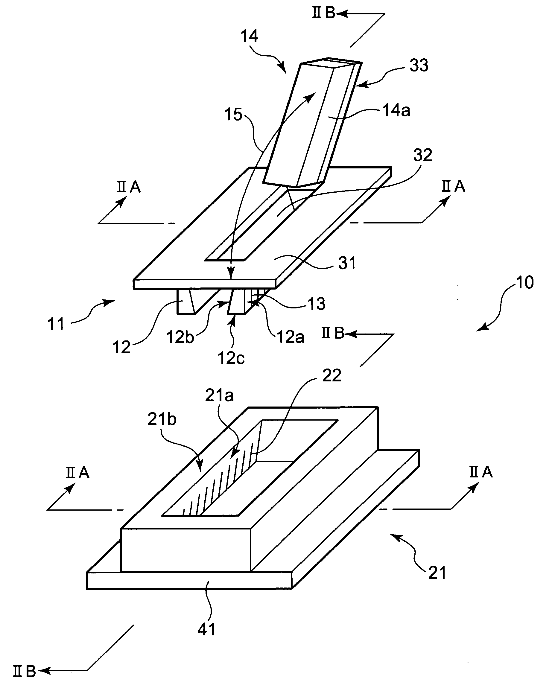
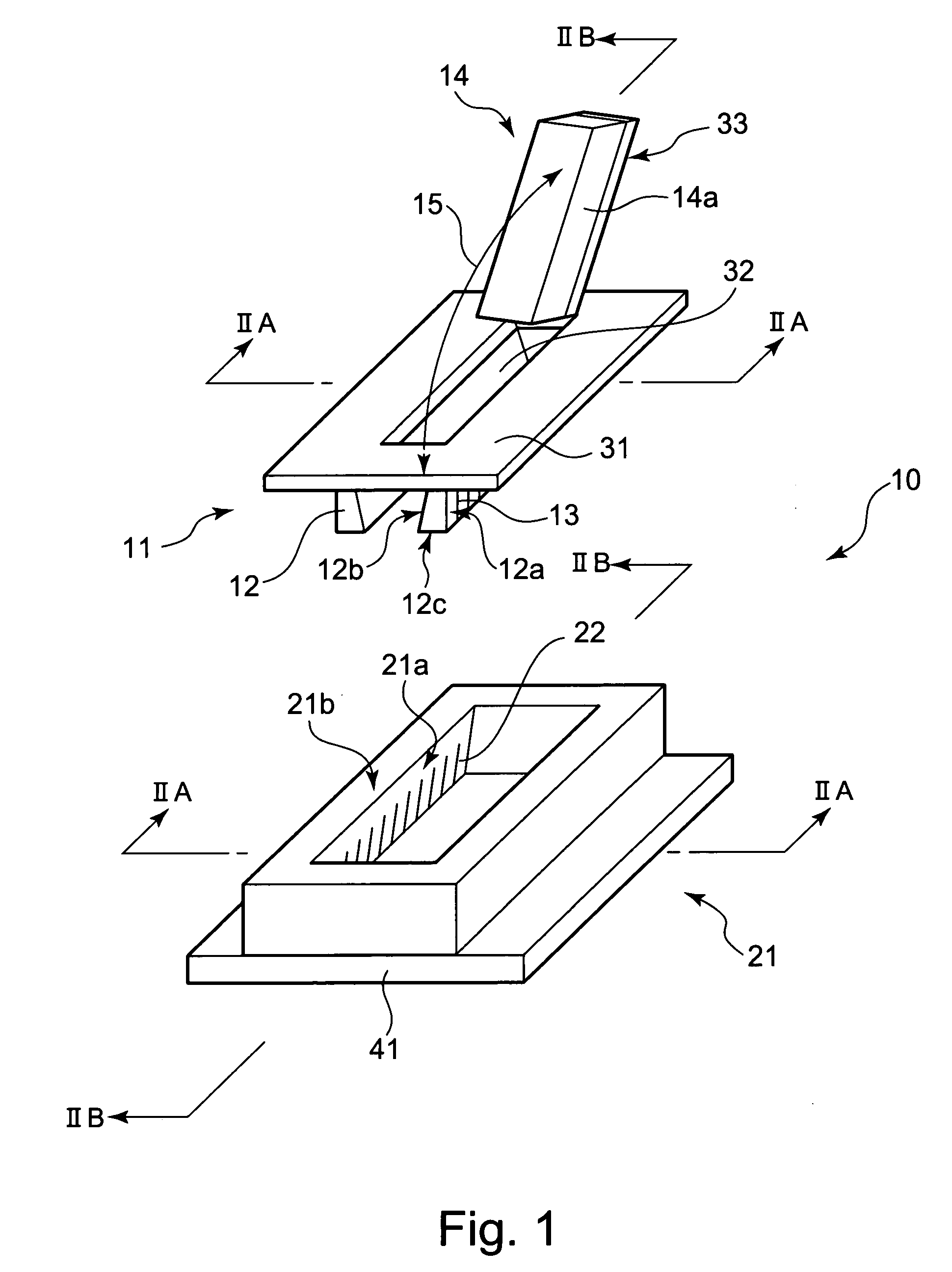
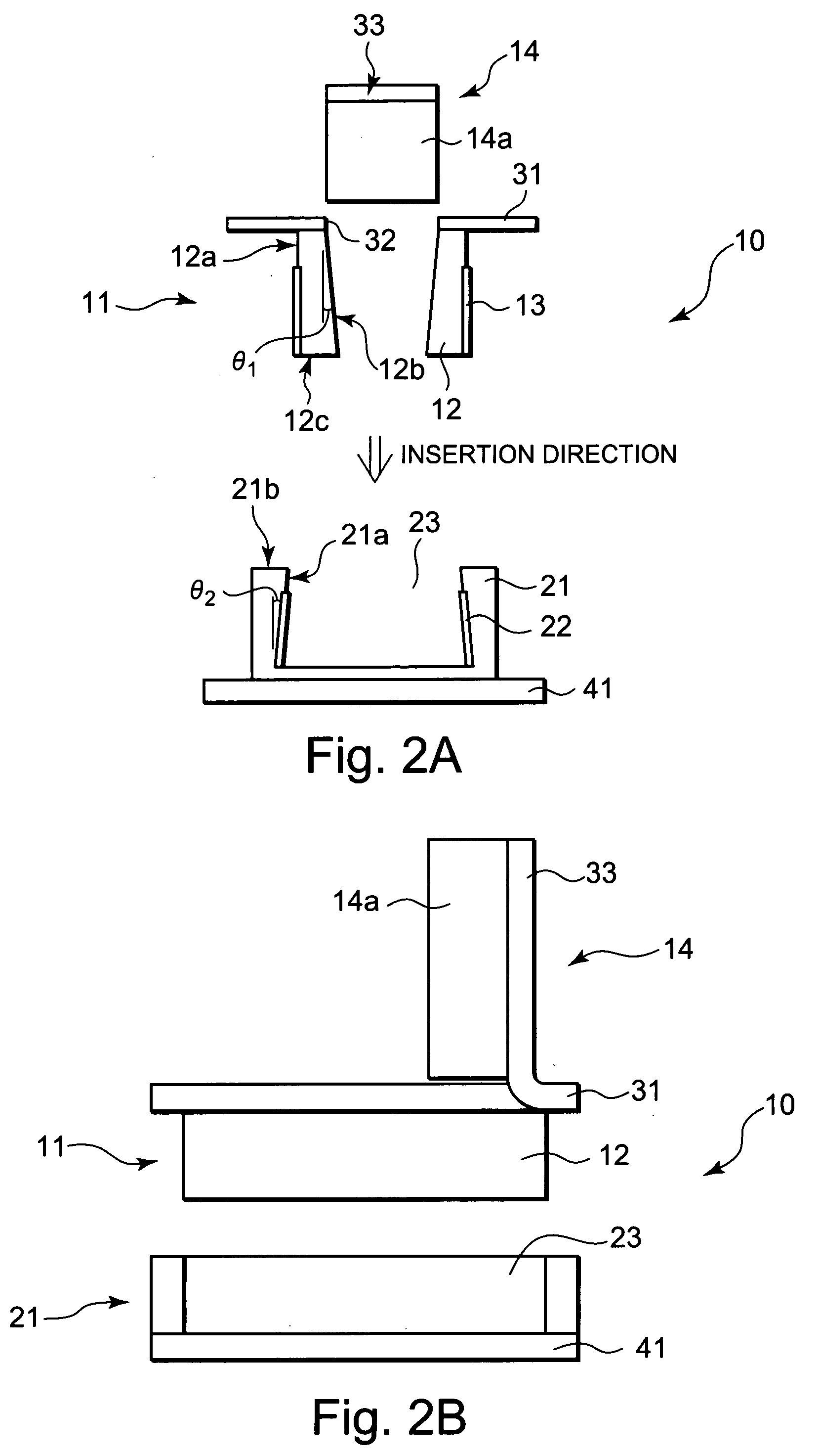
[0027]FIG. 1 is a perspective view showing a configuration of a connector according to an embodiment of the present invention. FIG. 2A is a cross-sectional view taken along the line IIA-IIA in FIG. 1. FIG. 2B is a cross-sectional view taken along the line IIB-IIB in FIG. 1. A connector 10 includes a plug 11, a socket 21 and a locking member 14 for locking the plug 11 i...


PUM


Abstract

A connector includes i) a plug including a pair of connecting members configured to connect the plug to a socket, a through-hole formed at a portion between the pair of connecting members, and plug contacts arranged on outer side faces of the respective connecting members, ii) a socket including a recess portion configured to receive the plug, and socket contacts arranged on inner side faces of the recess portion, and iii) a locking member configured to lock the plug into the socket, expanding the pair of the connecting members outward so as to contact each of the outer side faces of the connecting members onto a corresponding one of the inner side faces of the recess portion by inserting between the pair of the connecting members via the through-hole, and thereby bringing the plug contacts into contact with the socket contacts.

Description

BACKGROUND OF THE INVENTION[0001]1. Field of the Invention[0002]The present invention relates to a connector and a method of connecting the connector, and particularly to a connector mounted on a printed wiring board and a method of connecting the connector.[0003]2. Description of the Related Art[0004]A connector has heretofore been used as means which connects electrical circuits formed respectively on printed wiring boards to each other. FIG. 4 is a perspective view showing a configuration of a conventional connector. A connector 100 includes a male plug 101 and a female socket (a receptacle) 103. The plug 101 is mounted on a surface of a printed wiring board 105, and the socket 103 is mounted on a surface of another printed wiring board 106. The plug 101 includes a plurality of contacts (connections) 102 used for electrical connection on each of outer side faces 101a of the plug 101. On the other hand, the socket 103 includes a plurality of contacts (connections) 104 used for the...

Claims


Application Information

Patent Timeline
Patent Type & Authority Applications(United States)
IPC IPC(8): H01R13/44H01R12/82
CPCH01R13/639H01R12/716H01R12/52
Inventor UCHIDA, TOSHIO
Owner VISTA PEAK VENTURES LLC
Why Eureka
Eureka Blog
Learn More