Protector with sensor and method of molding end part of the same

一种防护装置、传感器的技术,应用在密封装置、测量装置、测量装置外壳等方向,能够解决电路短路、安装到模具上的作业困难、粘接不良等问题,达到稳定密封性能、缩短作业时间、作业容易的效果

Active Publication Date: 2015-09-23
NISHIKAWA RUBBER
View PDF4 Cites 0 Cited by
  • Summary
  • Abstract
  • Description
  • Claims
  • Application Information

AI Technical Summary

Problems solved by technology

[0013] However, if the connection parts M, M of the two core wires 31, 32 connected by resistance welding or soldering and the lead wires 36, 36 are immersed in water at the lower terminal portion of the protective device 10 with sensors, It may cause a short circuit in the connected circuit and cause a malfunction.
[0014] Therefore, it is conceivable to use the sealant (adhesive) made of epoxy resin described in Patent Document 1 to firmly fix the connection parts M and M, but there are problems as follows: a new bonding process is required, and a new bonding process is required. The curing time is several minutes to several hours. If the adhesive is used more, it will become the cause of poor adhesion.
In addition, the use of the adhesive tends to vary, and it is difficult to fix the connecting parts M and M in a stable state.
[0015] In particular, if the connection parts M and M are not fixed in a stable state, the shape of the product will be deviated when the product is injection molded later.
[0016] In addition, it is conceivable to double-cover the connecting parts M and M by using hot-melt molding described in Patent Document 2, but additionally, a support member such as a member for connecting the wirings is required, and there is also a problem in terms of heat resistance. problem, the mold release property is also poor
[0017] In contrast to this, as Figure 11 As shown, it can be considered to cover the connecting parts M, M of the core wires 31, 32 and the wires 36, 36 and the other end side of the insert 25 with an injection-molded primary sealing layer 101, but the covering parts of the wires 36, 36 37, 37 is very difficult to install on the mold

Method used


Image

  • Protector with sensor and method of molding end part of the same
  • Protector with sensor and method of molding end part of the same
  • Protector with sensor and method of molding end part of the same

Examples


Embodiment Construction

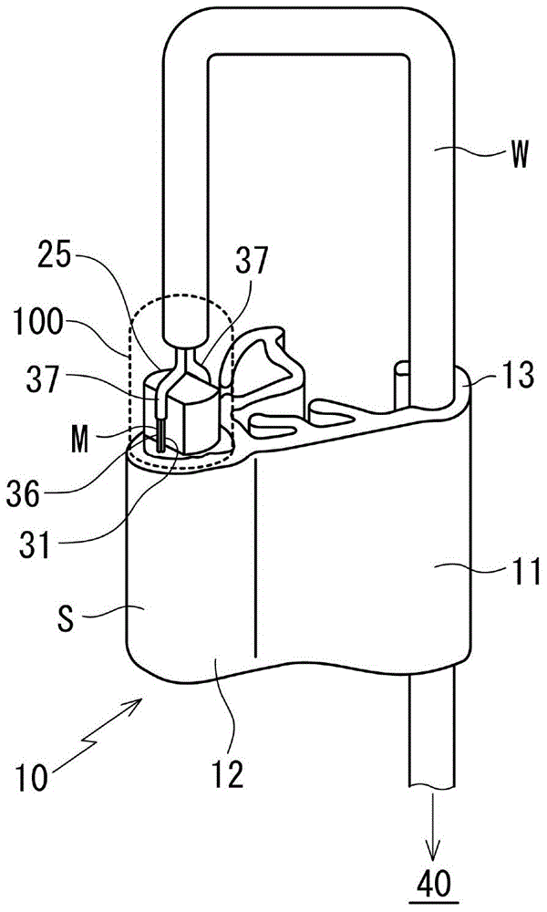
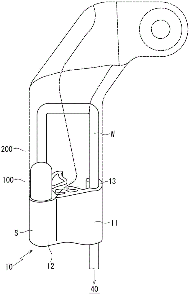
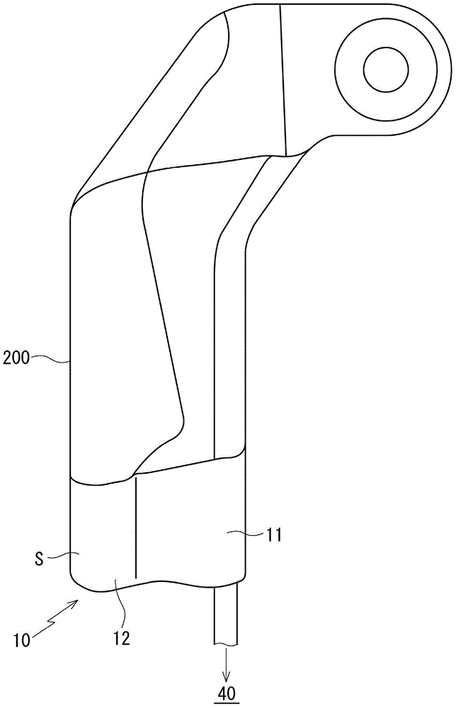
[0077] With reference to the drawings, the protective device with sensor according to the embodiment of the present invention will be described.

[0078] The protective device 10 with a sensor according to the embodiment of the present invention is installed in the Figure 5 The front end surface of the sliding door 1 on a car that opens and closes the opening of the car body as shown in the sliding door 1 and protrudes toward the front side of the car body, the guard 10 is equipped with a sensor (pressure sensitive sensor) S, which The sensor (pressure sensitive sensor) S detects a part of the human body (fingers, hands and feet) and other foreign objects between the sliding door 1 and the opening on the vehicle body side (there is also a front door (side door)). Output the corresponding electronic signal, in Figure 7 to Figure 10 Although the part shown has the same structure as the part shown in the previous example, the structure of the terminal part of the protective device ...


PUM


Abstract

A protector with a sensor is installed on a sliding door for detecting an object by touch between two core wires in a hollow part. In a terminal part of the protector with the sensor, the core wires drawn out are connected with leads joined with a control unit. A primary seal is formed by means of injection moulding for covering wire connection parts and another end side of an insert while also covering a skin of a wire harness which ties and coats the two leads. A secondary seal is formed by means of the injection molding for coating a part formed with the primary seal and for forming an external shape of a prod uct.

Description

Technical field [0001] The present invention relates to a protective device with a sensor and a method for forming the end of the protective device, wherein the protective device with a sensor is assembled with a sensor, and the sensor is installed along a station wagon, a single van, etc. When a foreign object such as a finger or the like is caught between the opening and closing object of the opening of the vehicle body such as a sliding door or a back door that moves back and forth, or a sunroof, the corresponding signal is output to detect the presence of the foreign object . Background technique [0002] In such Figure 5 The station wagon shown in this way uses the sliding door 1 (or back door) to open and close the opening of the car body or such as Image 6 In an automobile that uses a sunroof 2 to open and close the opening of the vehicle body as shown, sensor-equipped guards 10 and 20 are installed. [0003] For example, a protective device 10 with a sensor is installed o...

Claims


Application Information

Patent Timeline
Patent Type & Authority Applications(China)
IPC IPC(8): B60J5/00B60J1/00B60R16/02B29C45/14
CPCB60R16/0215B60J10/0057H01H3/142H01H9/04E05Y2600/40E05Y2800/46E05F15/44E05F15/443B60J10/273B29C45/14065B29K2019/00B29L2031/3055E06B7/36G01D5/14G01D11/16G01D11/24G01L1/005
Inventor 松本美智彦平川雄三
Owner NISHIKAWA RUBBER
Why Eureka
Try Eureka