Flexible Wicking Membrane

a wicking membrane, flexible technology, applied in the direction of joints tightening/covering, construction, building components, etc., can solve the problems of air leakage around building openings, most common failure points of unwanted air and/or moisture in building envelopes, exterior and interior damage, etc., to improve water flow and improve the first conformance

Inactive Publication Date: 2008-01-17
PROTECTO WRAP
View PDF15 Cites 5 Cited by
  • Summary
  • Abstract
  • Description
  • Claims
  • Application Information

AI Technical Summary

Benefits of technology

[0009]According to another arrangement, a utility is provided for forming a sill pan on a sill surface in an opening of a building structure. The utility includes disposing a flexible membrane across the length of a generally horizontal sill surface. Such a sill surface is typically disposed between first and second upright members (e.g., studs). In addition to being disposed across the length of the sill surface, the flexible membrane may, but not necessarily, include a first end that extends at least partially up a first upright member and a second end that extends at least partially up the second upright member. A rearward edge of the membrane (e.g., disposed towards the inside of the structure) that is disposed between the first and second uprights may be folded transverse to the generally horizontal sill surface. This resulting transverse portion of the membrane forms a barrier or back dam between the first and second uprights. This back dam prevents water on the sill from infiltrating into the building structure.
[0014]According to another arrangement, a utility is provide wherein a back dam material is connected to the waterproof membrane. In such an arrangement, a spacer material may be disposed on the bottom surface of the membrane to provide a back dam along the rearward edge (e.g., inside edge) of a sill surface. In such an arrangement, the flexible membrane may be disposed across the length of a generally horizontal sill surface disposed between first and second upright members. The flexible membrane may be of a length that allows a first end portion of the membrane to extend at least partially up the first upright member and a second end portion of the flexible membrane to extend at least partially up the second upright member. To allow for better conformance of the first and second end portions of the membrane to the upright members, the spacer material disposed on the bottom surface of the flexible membrane may be removed from the bottom surface of the first and second end portions. At this time, a release sheet may be removed from at least a portion of the bottom surface of the flexible membrane to expose a bottom adhesive surface, and that bottom adhesive surface may be contacted to the sill surface and / or upright members.
[0015]In one arrangement, the spacer material may be disposed across the length of the sill surface between the first and second upright members in order to provide higher elevation at the rearward edge of the sill and thereby provide a positive slope to drain water to the front of the sill and out of the building structure. Accordingly, wicking material may be connected to the top surface of the membrane to improve water flow.
[0017]In one arrangement, only a portion of the width of the spacer is initially adhered to the membrane. Such partial adherence may facilitate removal of portions of the spacer from the portions of the membrane that will extend at least partially up the upright members. In such an arrangement, one or more release liners may allow for full adherence of the spacer to the membrane after desired portions of the spacer are removed.
[0019]In one arrangement, the first and second ends of the third membrane are adhered to the first and second membranes, respectively. In one arrangement, the bottom surface of the third membrane is an adhesive surface. In such an arrangement, a release sheet may be removed from the bottom surface, and the membrane may be adhered to the first and second membrane as well as the sill surface. In one arrangement, the third membrane is cut to a length that corresponds with the length of the sill between the first and second upright members. To further enhance the waterproof qualities of the interface between the respective membranes, a sealant may be applied along the interface therebetween.

Problems solved by technology

One of the most common failure points for unwanted air and / or moisture in a building envelope is around doors and windows.
Controlling air and / or moisture is a serious concern, which may result in exterior and interior damage if not prevented or corrected in a timely manner.
In addition, heat losses caused by air leakage around building openings have taken on new significance due to today's high energy costs.
However, over several years, such caulking typically cracks, as it cannot withstand the constant expansion and contraction of the window.
Some studies indicate that after several years in operation, a majority of all windows will leak through the window flange or the window itself.
This water leakage can lead to structural damage such as rotting of the windowsills and mold.

Method used


Image

  • Flexible Wicking Membrane
  • Flexible Wicking Membrane
  • Flexible Wicking Membrane

Examples


Embodiment Construction

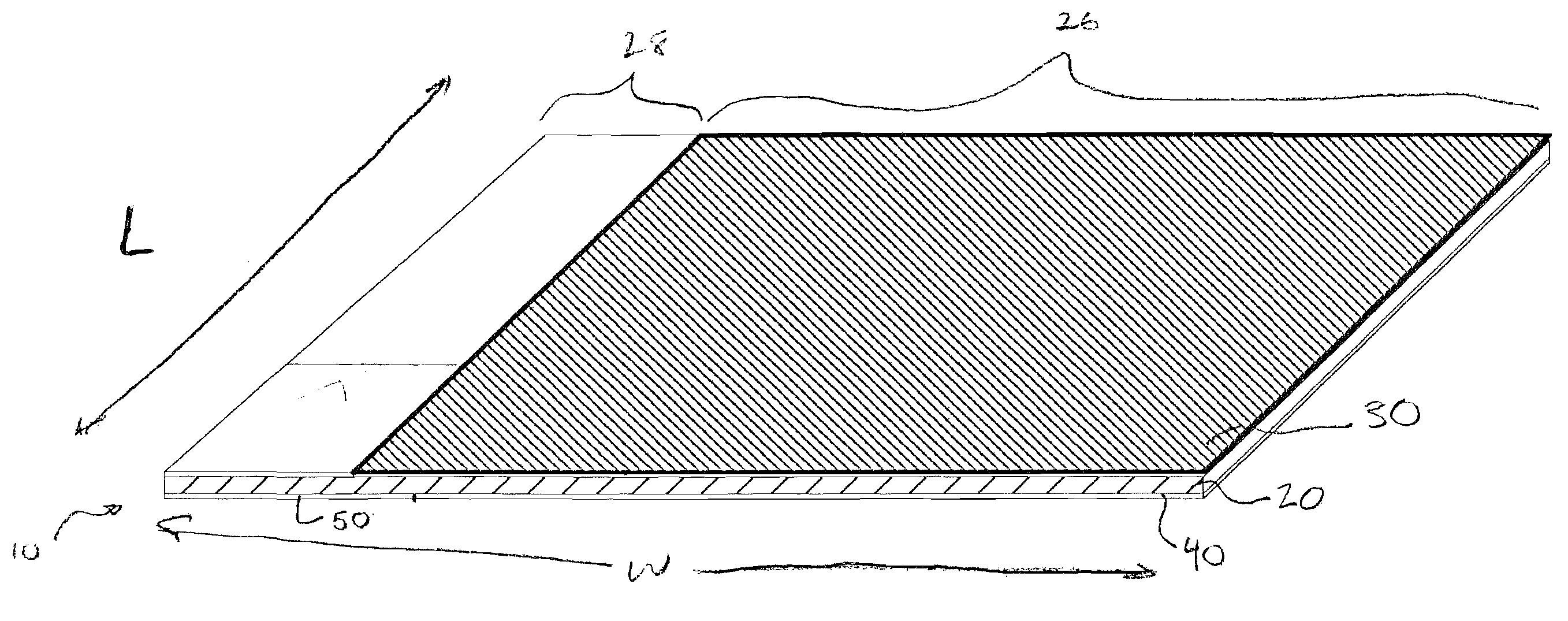
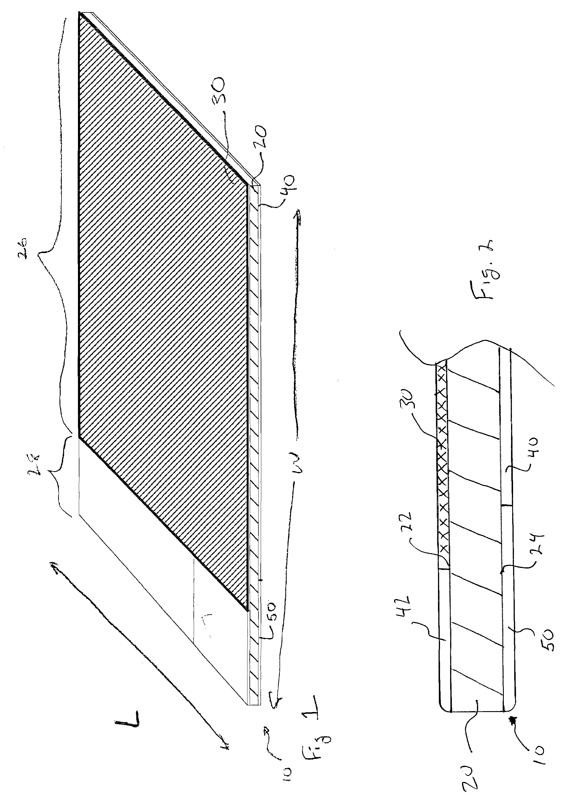
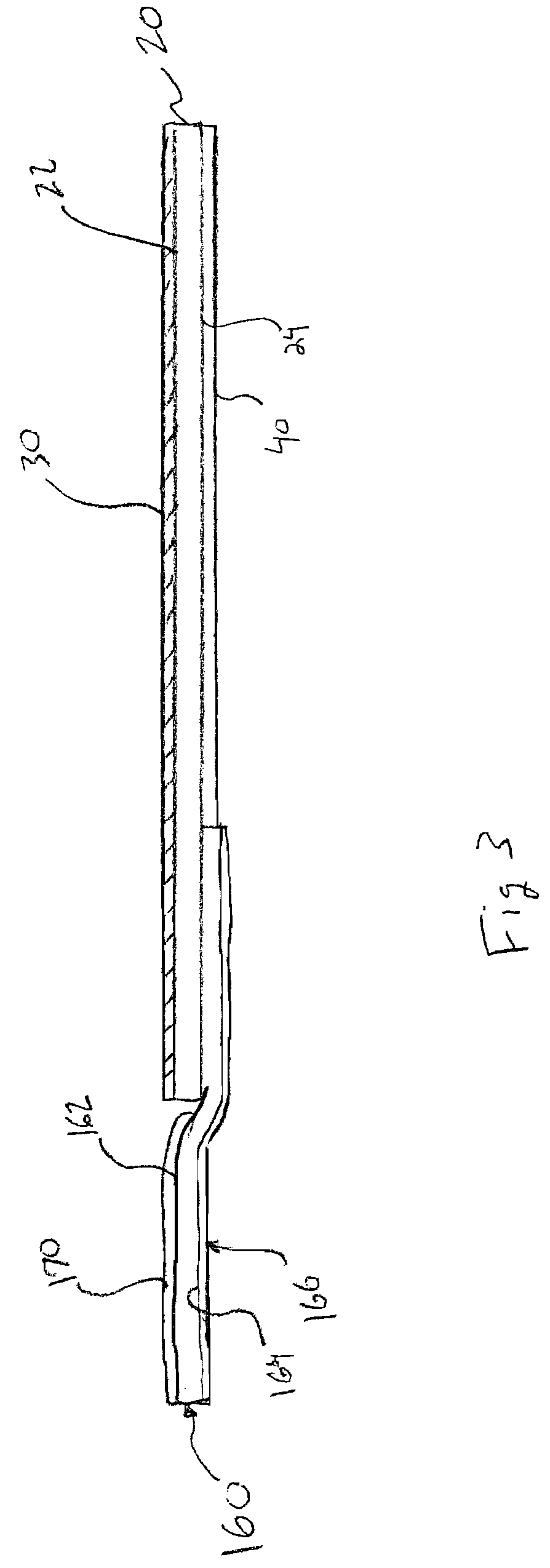
[0034]Reference will now be made to the accompanying drawings, which at least assist in illustrating the various pertinent features of the present invention. In this regard, the following description that utilizes a flexible membrane to form a sill pan in a window opening is presented for purposes of illustration and description. Furthermore, the description is not intended to limit the invention to the form disclosed herein. Consequently, variations and modifications commensurate with the following teachings, and skill and knowledge of the relevant art, are within the scope of the present invention. It will be appreciated that various aspects of the invention have utility for applications other than forming sill pans for windows and doors, for example, applications where it is desirable to remove moisture from a structure. The embodiments described herein are further intended to explain the best modes known of practicing the invention and to enable others skilled in the art to util...


PUM


Abstract

Disclosed herein are various waterproof membranes that may be applied to a sill surface of an opening in a building structure to waterproof that surface as well as direct water that penetrates through the opening out of the structure. Generally, one or more flexible waterproof membranes are adhesively applied to the sill surface for purposes of waterproofing that surface. Such membranes may further incorporate a back dam structure that is disposed proximate to the rearward edge of a sill plate (i.e., disposed toward the interior of the structure) to direct water towards the front edge of the sill plate (i.e., toward the outside of the structure). Further, such membranes may include wicking material on one or more surfaces to allow for directing water out of a building structure. In various arrangements, one or more flexible membranes may be utilized to create an open fronted sill pan.

Description

FIELD OF INVENTION[0001]The present invention generally relates to building products and, more particularly, pertains to an impermeable membrane that is adapted to waterproof a surface and wick moisture away from that surface.BACKGROUND OF THE INVENTION[0002]One of the most common failure points for unwanted air and / or moisture in a building envelope is around doors and windows. Controlling air and / or moisture is a serious concern, which may result in exterior and interior damage if not prevented or corrected in a timely manner. In addition, heat losses caused by air leakage around building openings have taken on new significance due to today's high energy costs. Sealing such openings has typically been accomplished by caulking or using putty-like compound around openings between door and window frames to seal the gaps and prevent inward seepage of air and / or water into the building.[0003]In window installations, caulking around the window has been the known installation and applica...

Claims


Application Information

Patent Timeline
Patent Type & Authority Applications(United States)
IPC IPC(8): E06B3/26
CPCE06B2001/628E06B1/62
Inventor HOPKINS, JOHN R.FORD, JAMES SCOTT
Owner PROTECTO WRAP
Why Eureka
Try Eureka