Dust collecting unit of vacuum cleaner

a technology of dust collector and vacuum cleaner, which is applied in the direction of liquid degasification, auxillary pretreatment, separation process, etc., can solve the problems of air not being able to easily pass through the filter, the dust separated from the air cannot be easily moved down to the dust storage, and the filter installed in the dust separating unit is contaminated by light dust, etc., to achieve the effect of improving the efficiency of the dust separating unit, easy discharge and smooth passage through the penetration hol

Active Publication Date: 2008-01-17
LG ELECTRONICS INC
View PDF4 Cites 19 Cited by
  • Summary
  • Abstract
  • Description
  • Claims
  • Application Information

AI Technical Summary

Benefits of technology

[0021] According to the present invention, the dust guide passage guides dust separated from air to be discharged from the dust separating unit in a tangential direction of the dust separating unit, so that the efficiency of the dust separating unit can be improved.
[0022] That is, separated dust is discharged from the dust separating unit in the same direction as the swirling direction of air in the dust separating unit. Thus, relatively light dust particles as well as heave dust particles can be easily discharged from the dust separating unit. As a result, no dust remains in the dust separating unit.
[0023] Since light dust particles do not remain in the dust separating unit, a filter member disposed in the dust separating unit is not contaminated by the light dust. Thus, air can smoothly pass through penetration holes of the filter member, and therefore dust separating efficiency increases.
[0024] In addition, the dust guide passage is formed outside of the dust separating unit, and the movement direction of dust is changed in the dust guide passage, so that dust stored in the dust storage can be prevented from scattering back to the dust separating unit.

Problems solved by technology

However, since the dust is sent to the dust storage through the dust discharge hole formed in the barrier wall by gravity, relatively light dust particles remain in the dust separating unit although heavy dust particles are easily moved down to the dust storage by gravity.
Therefore, the dust separated from the air cannot be easily moved down to the dust storage.
Furthermore, since light dust particles remain in the dust separating unit, filter installed in the dust separating unit is contaminated by the light dust.
In this case, air cannot easily pass through the filter, and thus dust is not efficiently removed from the air.
Moreover, the dust moved back to the separating unit decreases the efficiency of the dust separating unit.

Method used


Image

  • Dust collecting unit of vacuum cleaner
  • Dust collecting unit of vacuum cleaner
  • Dust collecting unit of vacuum cleaner

Examples


Embodiment Construction

[0036] Reference will now be made in detail to the preferred embodiments of the present invention, examples of which are illustrated in the accompanying drawings.

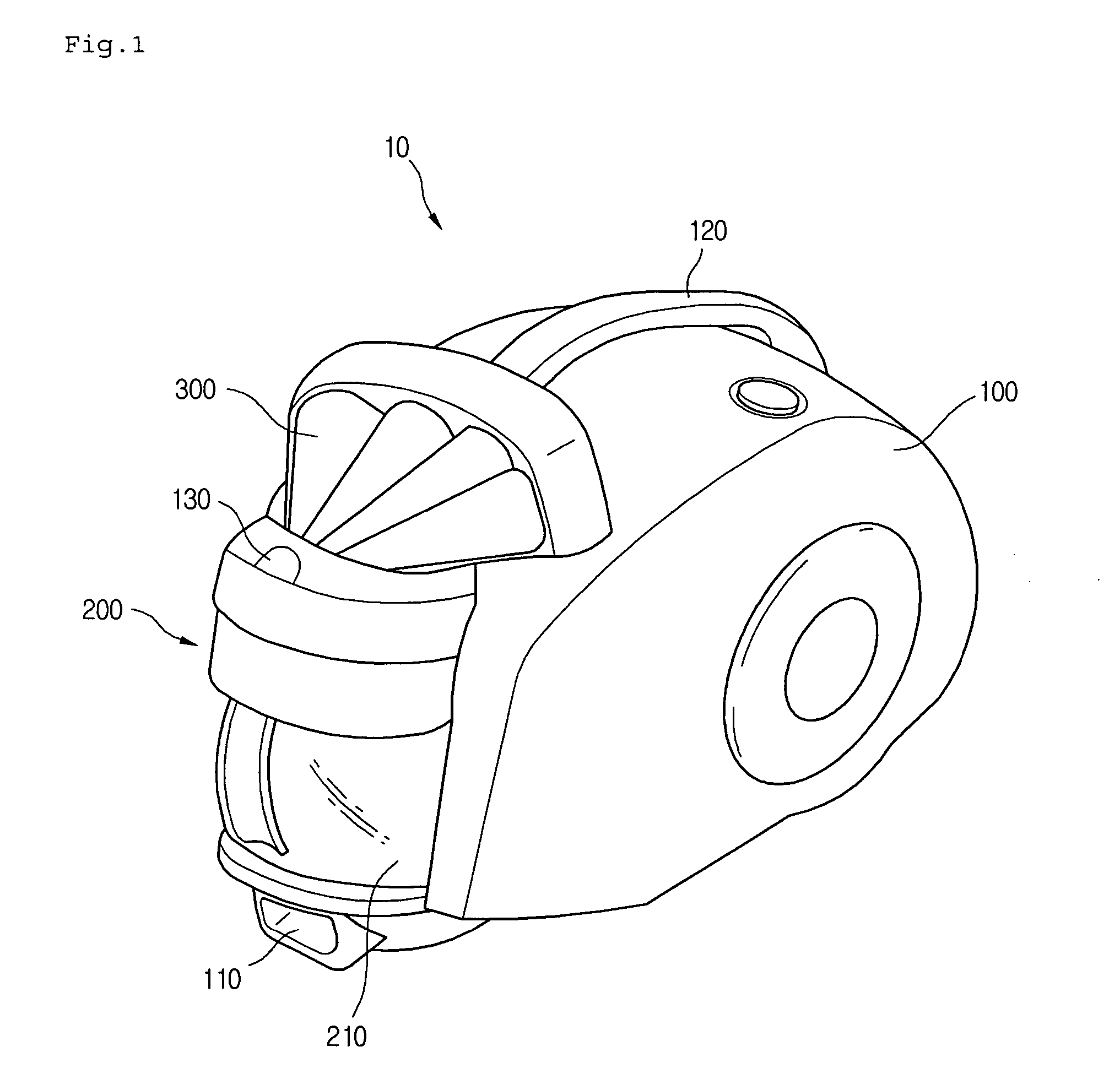
[0037]FIG. 1 is a perspective view illustrating a vacuum cleaner 10 according to an embodiment of the present invention.

[0038] Referring to FIG. 1, the vacuum cleaner 10 of the current embodiment includes a main body 100 and a dust collector 200 detachably installed to the main body 100.

[0039] The vacuum cleaner 10 further includes a suction nozzle (not shown) through which air containing dust is introduced into the vacuum cleaner 10, and a connection tube connecting the suction nozzle to the main body 100.

[0040] In the current embodiment, the suction nozzle and the connection tube have the same structure as those of the related art. Thus, descriptions thereof will be omitted.

[0041] In detail, the main body 100 includes a suction port 110 receiving air sucked through the suction nozzle. The main body 100 further includ...


PUM

PropertyMeasurementUnit
sizeaaaaaaaaaa
diameteraaaaaaaaaa
cross-sectional areaaaaaaaaaaa

Abstract

Provided is a dust collector of a vacuum cleaner. The dust collector includes a dust separating unit forming a separation space for separating dust from air, a collector body forming a dust storage for storing the dust separated in the dust separating unit, and a dust guide passage connecting the separation space to the dust storage and guiding the separated dust to be discharged from the separation space in a tangential direction.

Description

BACKGROUND OF THE INVENTION [0001] 1. Field of the Invention [0002] The present invention relates to a dust collector of a vacuum cleaner, and more particularly, to a dust collector of a vacuum cleaner, in which dust can be collected more efficiently and a backward flow of collected dust can be prevented. [0003] 2. Description of the Related Art [0004] Generally, a vacuum cleaner sucks air containing dust using a negative pressure generated by a suction motor installed in a main body, and then dust is separated from the air in the main body. [0005] Vacuum cleaners can be divided into a canister type vacuum cleaner and an upright type vacuum cleaner. A canister type vacuum cleaner includes a separate nozzle used for sucking air containing dust from a surface to be cleaned, a main body, and a connection tube connecting the separate nozzle to the main body. On the hand, an upright type vacuum cleaner includes a nozzle formed integral with a main body. [0006] Meanwhile, a vacuum cleaner...

Claims


Application Information

Patent Timeline
Patent Type & Authority Applications(United States)
IPC IPC(8): B01D45/16
CPCA47L9/1658A47L9/1683Y10S55/03B04C5/185B04C5/181A47L9/10A47L9/16
Inventor YUN, CHANG HOHA, GUN HOKIM, JIN YOUNGLEE, CHANG HOONSEO, JIN WOOK
Owner LG ELECTRONICS INC
Why Eureka
Try Eureka