Fireproof hose

a technology of fireproof hoses and hoses, applied in the direction of flexible pipes, rigid pipes, pipes, etc., to achieve the effect of efficient isolation effect and ease of deformation of fireproof hoses

Inactive Publication Date: 2008-01-17
HILTI AG
View PDF12 Cites 20 Cited by
  • Summary
  • Abstract
  • Description
  • Claims
  • Application Information

AI Technical Summary

Benefits of technology

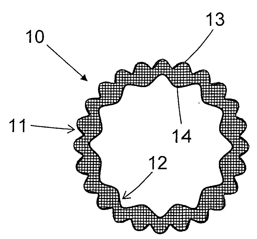
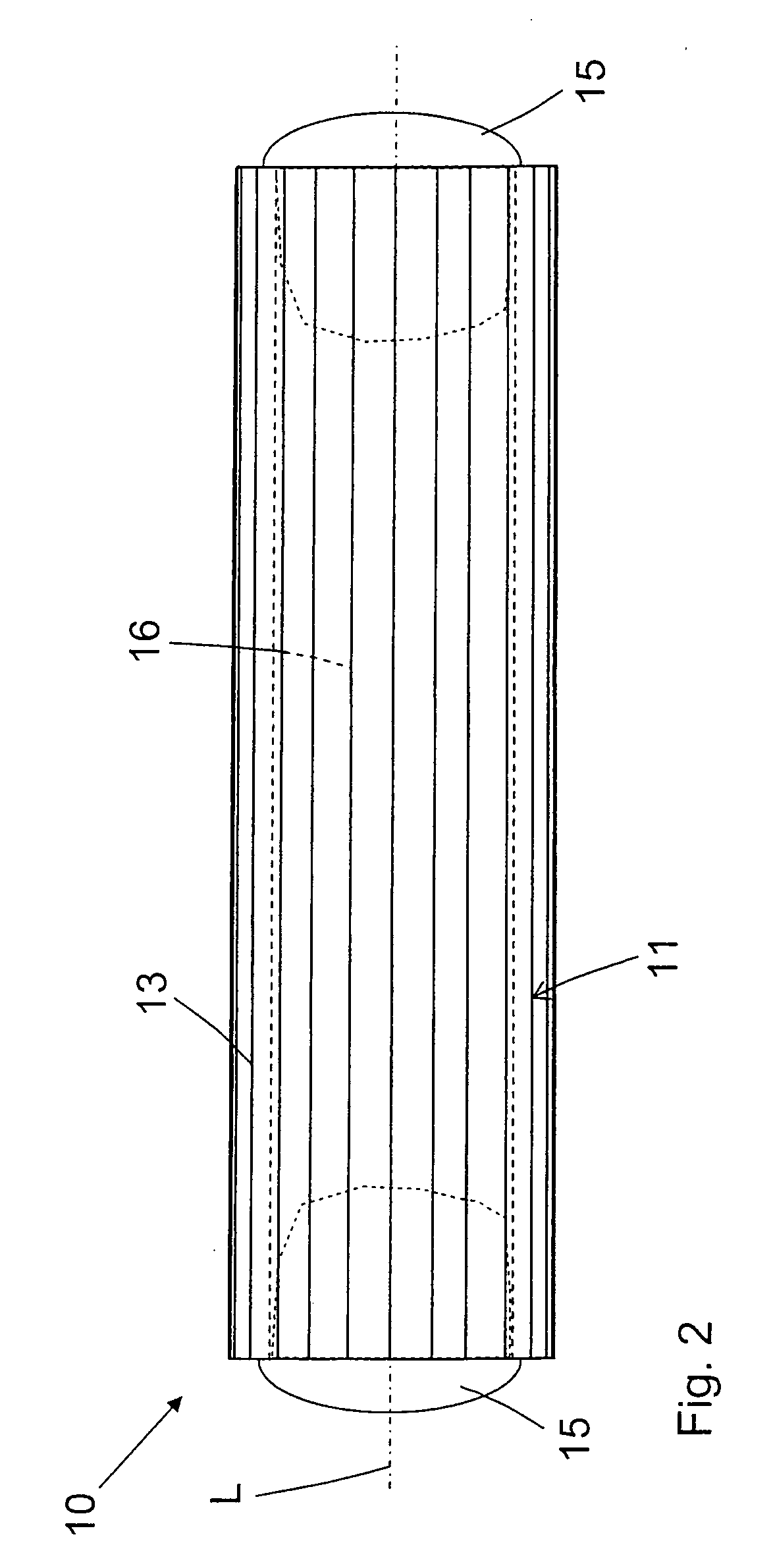
[0011]It is advantageous, when the profile is formed by a plurality of ribs extending in a longitudinal direction. When the fireproof hose is mounted in a hole in a constructional element, such as e.g., a wall, the ribs provide for an easier deformation of the fireproof hose, so that the hose can be inserted in holes or bores the diameter of which is smaller than the diameter of the fireproof hose. Here, with a deviation of the hole diameter, the tolerance region lies within several mm.
[0012]It is advantageous when the ribs are equidistantly spaced from each other and extend parallel to each other, which insure a uniform distribution of the ribs over the surface. This provides for uniform thermal and physical characteristics of the entire fireproof hose.
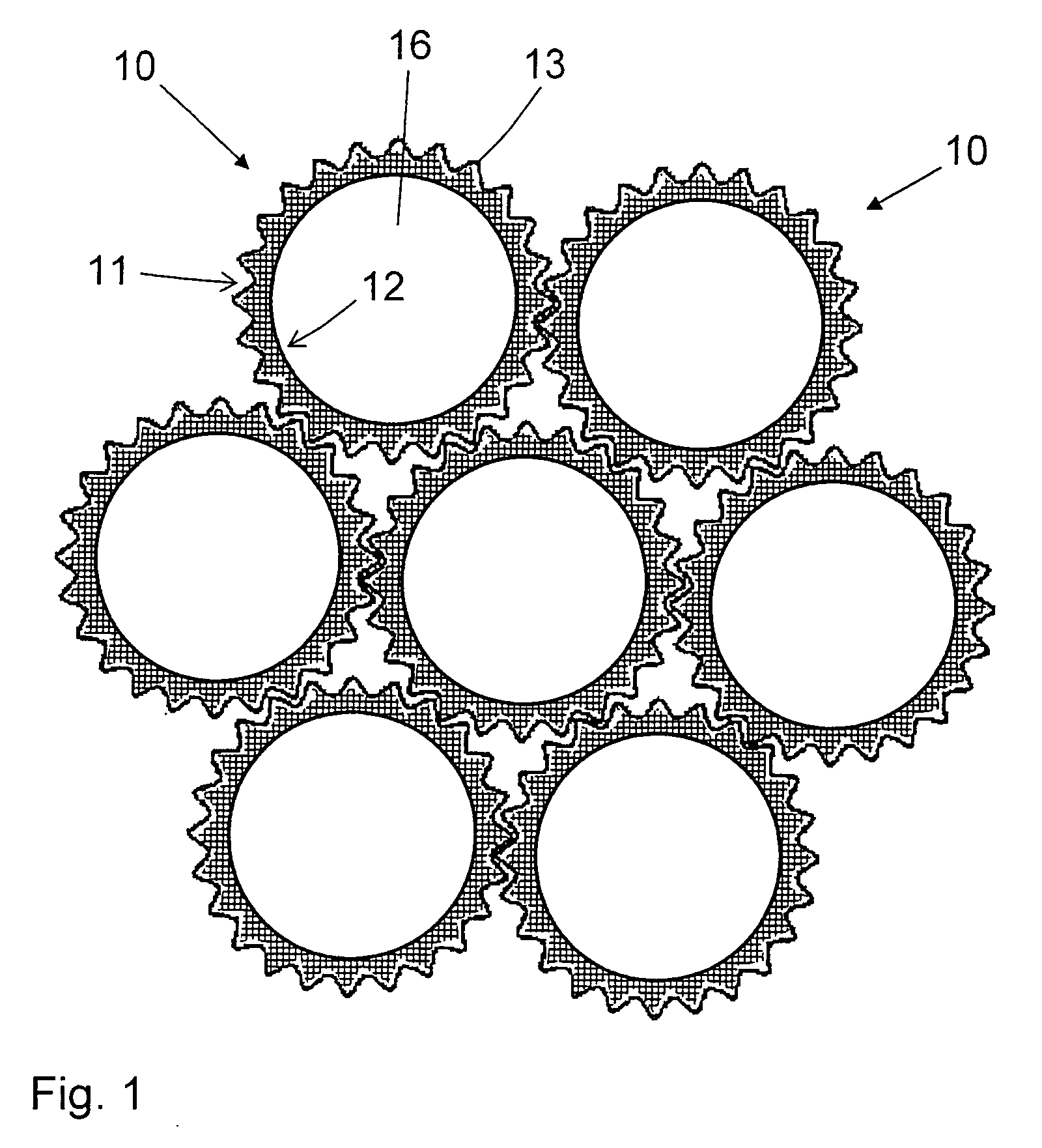
[0013]Advantageously, the ribs are provided on the outer surface of the fireproof hose. Thereby in addition to a positive thermal effect, there is provided a possibility for engagement of adjacent fireproof hoses with each other, with ribs of one hose engaging in respective grooves of an adjacent hose and vice versa. Thereby, groups or clusters of fireproof hoses can be formed which together can be mounted in a large opening or hole formed in a constructional element.
[0014]It is also advantageous when the ribs are formed on the inner surface of a fireproof hose. Thereby, in case of fire, a hot metal core of a cable, which extends through the hose, is held at a distance from the hose outer surface, which prevents collapsing of the material of the fireproof hose as it becomes weaker. The outer surface remains cooler as the contact with the hot copper core is prevented. Thereby, a more efficient isolation effect is achieved.
[0015]Advantageously, the ribs are provided on both the outer and inner surfaces of the fireproof hose. Thereby, a combined effect of providing ribs on the outer and inner surfaces is achieved.
[0016]A tooth-shaped formation of the ribs improves the above described possibility to combine fireproof hoses in groups or clusters, as tooth-shaped ribs can optimally engage with each other, in the same way as teeth of tooth gears engage each other.

Problems solved by technology

The drawback of the fireproof hose disclosed in EP 1 396 675 A1 consists in that in case of fire, it has, at its end remote from the fire center, only a small cooling effect and can be used primarily for a thermal isolation of a sheathable conduit having a relatively large thickness.

Method used


Image

  • Fireproof hose
  • Fireproof hose
  • Fireproof hose

Examples


Embodiment Construction

[0023]A fireproof hose 10 according to the present invention, a first embodiment of which is shown in FIGS. 1-2, is formed as an elastic body extending in a longitudinal direction L and formed of, e.g., a rubber-elastic material such as, e.g., rubber-like polymer with intumescent properties. As an intumescent component, an expandable graphite, e.g., or similar known intumescent material can be used.

[0024]On the outer surface 11 of the fireproof hose 10, there is formed a profile in form a plurality of first ribs 13 extending parallel to each other in the longitudinal direction L of the fireproof hose 10 and having, in the embodiment shown in FIGS. 1-2, a tooth-shaped triangular cross-section. The first ribs 13 improve thermal characteristics of the fireproof hose 10. The first ribs 13 are uniformly distributed on the outer surface 11 at a same distance from each other and insure an optimal isolation of an enveloped conduit or of a surrounded cable. As shown in FIG. 1, the tooth-shap...


PUM


Abstract

A fireproof hose (10) for passing conduits or cables through a constructional element is formed at least partially of an elastic and intumescent material and has a shaped profile provided on at least one of the outer surface (11) and the inner surface of the hose.

Description

BACKGROUND OF THE INVENTION[0001]1. Field of the Invention[0002]The present invention relates to a fireproof hose for passing conduits or cables through a constructional element and formed at least partially of an elastic and intumescent material and having outer surface and inner surface extending in a longitudinal direction.[0003]2. Description of the Prior Art[0004]As mentioned above, the fireproof hose of the type discussed above is used for passing a conduit or a cable through a constructional element, e.g., through a ceiling or a wall.[0005]European Publication EP 1 396 675 A1 discloses a fireproof hose the main component of which is thermally expandable graphite, thermally expandable rubber, or thermally expandable resin. The fireproof hose is slotted in a longitudinal direction in order to be able subsequently put it around a conduit. The upper surface of this fireproof hose is smooth.[0006]The drawback of the fireproof hose disclosed in EP 1 396 675 A1 consists in that in c...

Claims


Application Information

Patent Timeline
Patent Type & Authority Applications(United States)
IPC IPC(8): F16L11/12
CPCF16L5/04H02G3/0412F16L5/14H02G3/22H02G3/0481
Inventor PAETOW, MARIOMUENZENBERGER, HERBERTFOERG, CHRISTIAN
Owner HILTI AG
Why Eureka
Try Eureka