Penetration slider seal expansion joint apparatus and method

a slider seal and expansion joint technology, applied in the field of expansion joints, can solve the problems of limited or inexistent translational movement of the pipe orthogonal to the axis of the pipe with respect to the currently available expansion joints, and cannot allow unlimited pipe travel, etc., to ensure the safe and continuous operation of the power plant

Active Publication Date: 2008-01-17
EAGLEBURGMANN IND LP
View PDF4 Cites 1 Cited by
  • Summary
  • Abstract
  • Description
  • Claims
  • Application Information

AI Technical Summary

Benefits of technology

[0011] One or more embodiments of the invention comprise a penetration slider seal expansion joint apparatus and method. An expansion joint is an apparatus that is situated between a device and a pipe and allows for expansion and contraction at the joint in order to account for movement of the pipe relative to the device. Expansion joints are used for example at power plants in order to couple boilers to steam pipes that are used to rotate generators. For example, power plants are configured to operate using steam at approximately 1300 degrees and 700 PSI. Boiler exhaust systems operate at this temperature, but at much lower pressure, generally around one atmosphere. Boiler exhaust systems may also employ expansion joints. By utilizing an expansion joint at the boiler, ruptures in the joints between the boiler and pipes are avoided for example during earth quakes or due to thermal expansion or as a result of any other force which may occur at the joint. Expansion joints thus ensure the safe and continuous operation of the power plant.
[0012] Embodiments of the invention may be used in power plant exhaust systems for example. Embodiments of the invention are constructed from a case pipe comprising an inner ring, a sliding ring formed to house a plurality of seals, and a flange that couples with the case pipe to hold the sliding ring in place. These three main elements are described further in the detailed description and accompanying figures below. Utilizing this configuration provides numerous advantages. Embodiments of the invention allow limited leakage but provide unlimited travel of the pipe along the axis of the apparatus, unlimited rotation of the pipe about the axis of the pipe, a configurable amount of translational movement orthogonal to the axis of the pipe, and a configurable amount of angular deviation (the amount of angle differing from the axis of the pipe with respect to the device to which it attaches). The amount of translational movement allowed orthogonal to the axis of the pipe is controlled by the size of the gaps employed in the case pipe and flange as will be further described below. Embodiments of the invention allow for ease of maintenance since the apparatus may be disassembled and worked on without cutting metal or welds. In addition, embodiments of the invention may be constructed in any size. Embodiments of the invention may also be configured in series and / or recursively stacked to provide a level of redundancy heretofore unobtainable.
[0014] Various materials may be utilized for the seals. In one or more embodiments of the invention, the seals are made of braided metallic wire, for example 309 stainless steel. Although porous, seals made from this type of material comprise memory that allows for the inner and outer seals to perform properly and in addition fill with contaminants as time passes which actually improves the seals by allowing less matter to escape past the seals. Depending upon the environment in which the embodiment is used, rubber seals, silicon seals, seals comprising ceramic, fiberglass and / or metallic materials may be substituted or used in combination in keeping with the spirit of the invention. By utilizing an inner seal beyond memory and at least one outer seal within memory, unlimited travel and rotation is achieved, with configurable translation and angular deviation and minimal leakage. Maintaining the seals is easily achieved without cutting welds.

Problems solved by technology

Current expansion joints do not allow for unlimited travel of pipe to and from a device and do not allow for unlimited rotation of a pipe with respect to a device.
In addition, translational movement of pipe orthogonal to the axis of the pipe with respect to currently available expansion joints is also limited or non-existent depending on the particular joint.
These joints are limited in the amount of travel of the pipe along the pipe axis, rotation about the pipe axis and translation orthogonal to the pipe axis that they can accommodate.
In addition, bellows type expansion joints have a limited number of cycles that they are able to endure before failing.
Maintenance of such an apparatus is thus an expensive endeavor.
This design makes use of two O-rings inside grooves 42 that are incapable of handling high pressure and / or temperature due to their configuration and materials of construction.
Translational movement orthogonal to the axis of the pipe is not possible with this type of expansion joint as there is no where for the inner sleeve to move to.
In addition, the device limits the length of travel of the two sleeves by employing stop members at the ends of the sleeves that limit the maximum amount of travel permitted by the device.
This device suffers from the limitations of both of the previous devices in that the bellows are limited to a number of cycles and provide only limited horizontal travel without enabling unlimited rotation and provide negligible translation movement of the pipe to which the expansion joint is coupled.

Method used


Image

  • Penetration slider seal expansion joint apparatus and method
  • Penetration slider seal expansion joint apparatus and method
  • Penetration slider seal expansion joint apparatus and method

Examples


Embodiment Construction

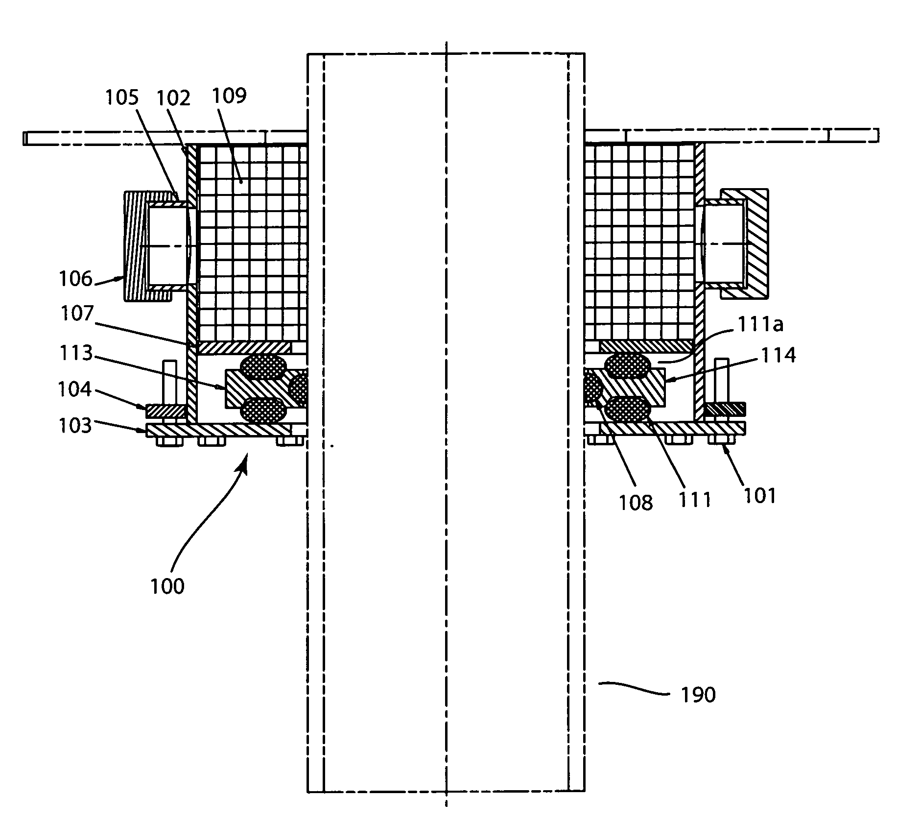
[0043] A penetration slider seal expansion joint apparatus and method will now be described. In the following exemplary description numerous specific details are set forth in order to provide a more thorough understanding of embodiments of the invention. It will be apparent, however, to an artisan of ordinary skill that the present invention may be practiced without incorporating all aspects of the specific details described herein. In other instances, specific features, quantities, or measurements well known to those of ordinary skill in the art have not been described in detail so as not to obscure the invention. Readers should note that although examples of the invention are set forth herein, the claims, and the full scope of any equivalents, are what define the metes and bounds of the invention.

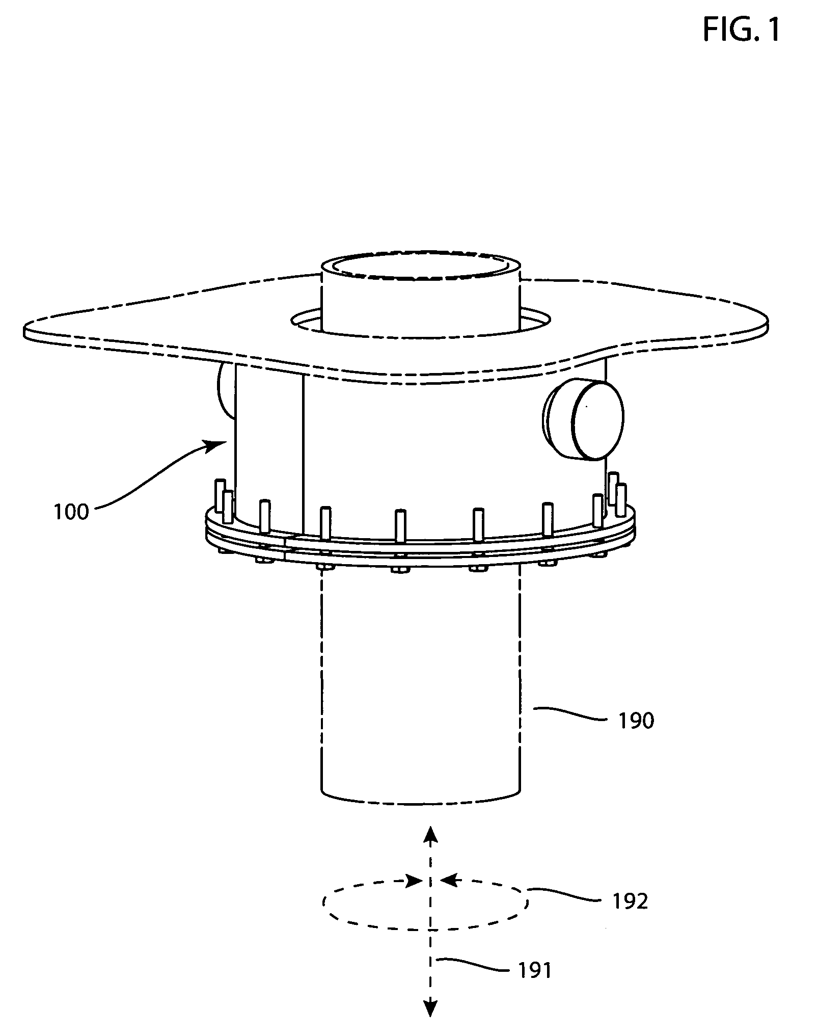
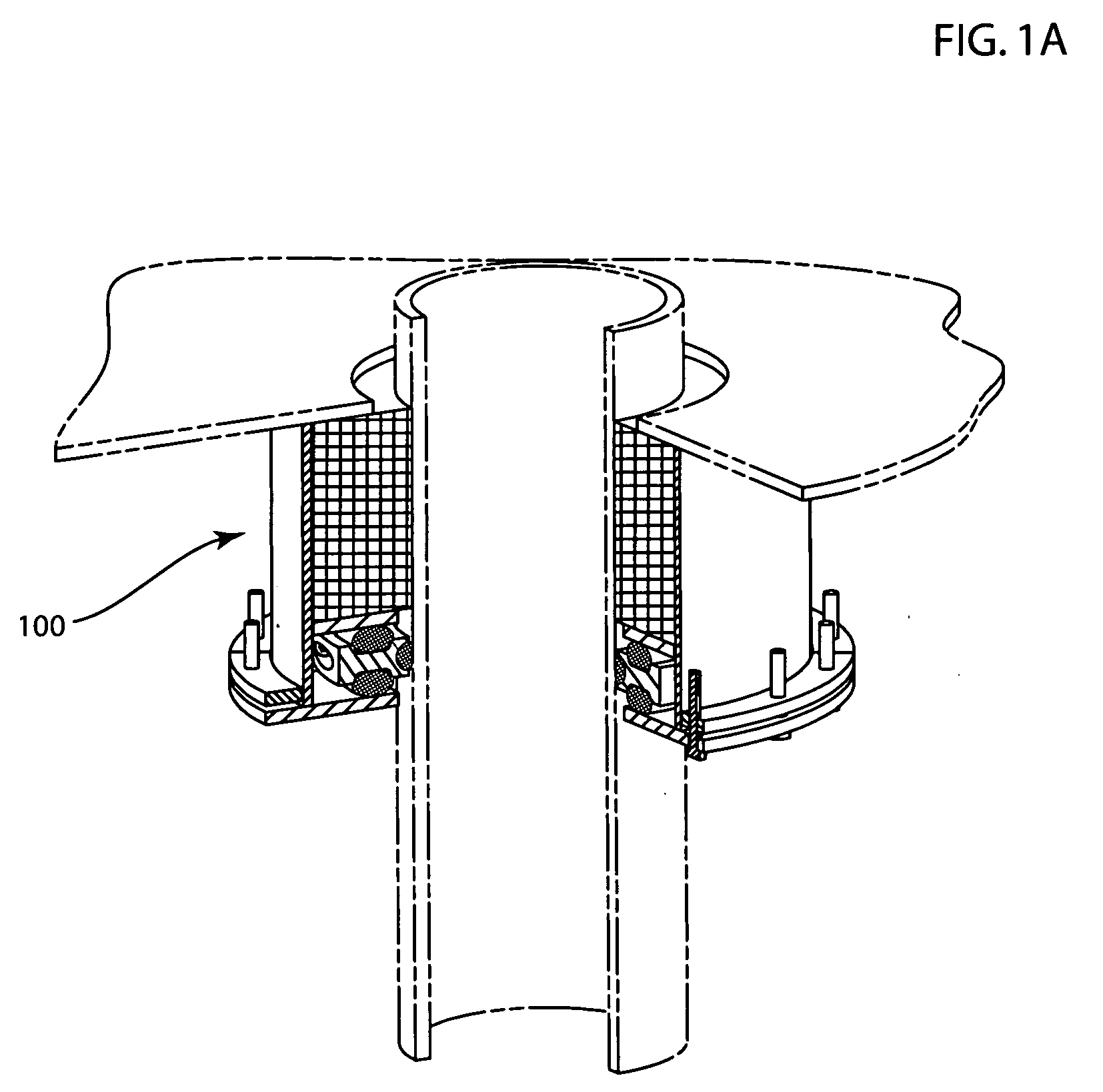
[0044]FIG. 1 is an isometric view of an embodiment of the penetration slider seal expansion joint 100. Pipe 190 may travel in an unlimited direction along pipe axis 191. Pipe 190 may rot...


PUM


Abstract

A penetration slider seal expansion joint apparatus and method. An expansion joint lies between a device and pipe and allows for movement at the joint. Embodiments utilize a case pipe, a sliding ring formed to house seals, and a flange that holds the sliding ring in place. A pipe contacts an inner seal inside the sliding ring which is compressed against the pipe beyond its memory and forms a tight seal, yet allows for pipe to move through the apparatus. At least one outer seal is compressed within its memory which allows for rotation of pipe and / or sliding ring relative to the apparatus about the axis of the pipe. Allows for unlimited travel of pipe and unlimited rotation. The apparatus becomes more efficient as contaminants fill the seals. Works below, at and beyond 1300 degree media, for example any liquid or gas. May be disassembled easily maintained.

Description

BACKGROUND OF THE INVENTION [0001] 1. Field of the Invention [0002] Embodiments of the invention described herein pertain to the field of expansion joints. More particularly, but not by way of limitation, one or more embodiments of the invention enable an expansion joint of unlimited expansion and rotation of a pipe coupled to embodiments of the invention while maintaining containment integrity at the joint. [0003] 2. Description of the Related Art [0004] There are a number of requirements and / or preferences associated with expansion joints. Expansion joints allow for the movement of a pipe with respect to a device to which the pipe is coupled and are required in some environments, for example power plants for safety and robust delivery of power. There are many other environments where expansion joints are used with pipe including commercial buildings, sewers and dams for example. [0005] Current expansion joints do not allow for unlimited travel of pipe to and from a device and do n...

Claims


Application Information

Patent Timeline
Patent Type & Authority Applications(United States)
IPC IPC(8): F16L27/00
CPCF16L27/125F16L27/10F16L27/12751Y10S285/917
Inventor BARBER, NEVILLE
Owner EAGLEBURGMANN IND LP
Why Eureka
Try Eureka