
Crushing device for belt conveyor and belt conveyor

A belt conveyor and crushing device technology, applied in conveyors, transportation and packaging, loading/unloading, etc., can solve the problems of production and operation stagnation, the inability of belt conveyors to carry bulk materials, and safety risks.

Pending Publication Date: 2022-04-29
NINGXIA TIANDI BENNIU IND GRP
View PDF0 Cites 0 Cited by
  • Summary
  • Abstract
  • Description
  • Claims
  • Application Information

AI Technical Summary

Problems solved by technology

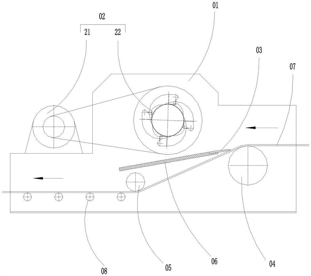
[0003] In the process of belt conveyor transporting materials, especially in underground mining and transportation, the conveyor belt needs to carry large pieces of material that have collapsed in the mine layer. In the roadway, large pieces of material often roll off the conveyor belt, resulting in roadway A large amount of bulky materials are often piled up and need to be cleaned manually, which increases the labor intensity of workers and poses a certain safety risk. At the same time, the bulky materials will cause the conveyor belt to be smashed or even torn during each unloading link of the belt conveyor. The belt phenomenon, resulting in the continuous increase of equipment maintenance costs and the stagnation of production and operation, brought great economic losses to the enterprise
[0004] At present, the traditional material crushing equipment cannot meet the supporting installation and use of the belt conveyor. In order to solve the above problems, it is urgent to develop a material crushing device suitable for the structural characteristics of the belt conveyor. Crushing in the process solves the current situation that the belt conveyor cannot carry bulky materials

Method used


Image

  • Crushing device for belt conveyor and belt conveyor
  • Crushing device for belt conveyor and belt conveyor
  • Crushing device for belt conveyor and belt conveyor

Examples


Embodiment Construction

[0023] The following will clearly and completely describe the technical solutions in the embodiments of the present invention with reference to the accompanying drawings in the embodiments of the present invention. Obviously, the described embodiments are only some, not all, embodiments of the present invention. Based on the embodiments of the present invention, all other embodiments obtained by persons of ordinary skill in the art without creative efforts fall within the protection scope of the present invention.

[0024] In the description of the present invention, it should be understood that the terms "upper", "middle", "outer", "inner", "lower", etc. indicate orientation or positional relationship, and are only for the convenience of describing the present invention and simplifying the description, It is not intended to indicate or imply that the components or elements referred to must have a particular orientation, be constructed and operate in a particular orientation, a...


PUM


Abstract

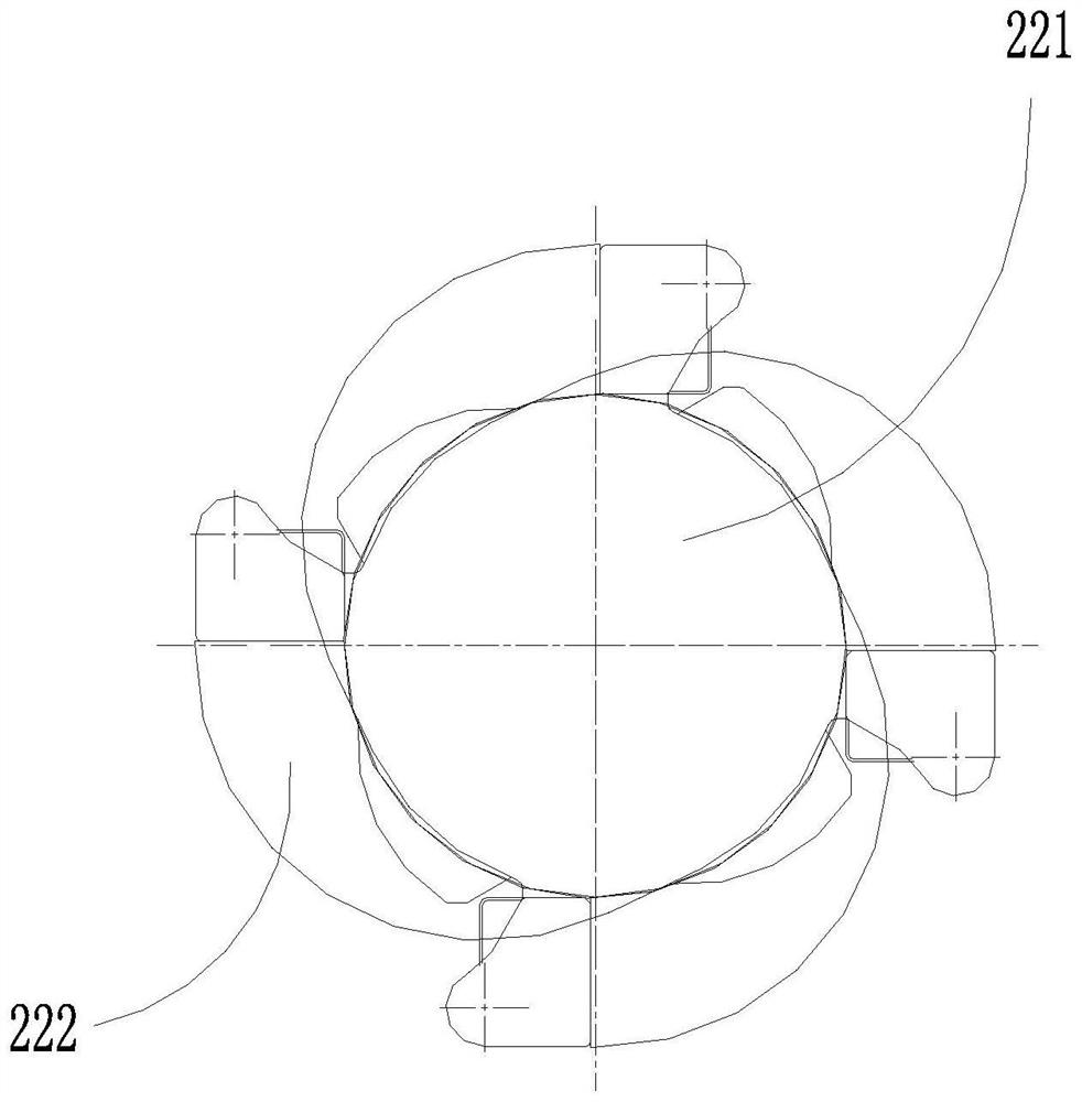
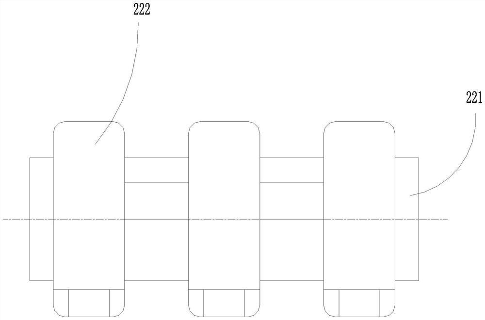
The crushing device for the belt conveyor comprises a crushing box body, a crushing assembly and a material distributing assembly, the crushing assembly is arranged on the upper portion in the crushing box body, a supporting roller is arranged in the crushing box body, a belt pressing roller is arranged in the crushing box body, a buffering carrier roller is arranged in the crushing box body, and a crushing lining plate is arranged in the crushing box body; the crushing lining plate is located between the crushing assembly and a belt of the belt conveyor, the crushing lining plate is inclined, one end of the material distributing assembly is attached to the surface of the belt of the belt conveyor, and the other end of the material distributing assembly is connected with the end, close to the supporting roller, of the crushing lining plate; when the large coal crushing device is used, large coals on the belt conveyor can be continuously crushed, the technical problem that the belt conveyor cannot carry large materials is solved, the problem that the large coals are scattered and accumulated in an underground roadway of a coal mine can be greatly solved, a belt can be prevented from being damaged by the large coals, and safe and continuous operation of equipment is guaranteed; the accident rate is reduced.

Description

technical field [0001] The invention relates to the technical field of coal mine conveying equipment, in particular to a crushing device for a belt conveyor and the belt conveyor. Background technique [0002] In recent years, as the application range of belt conveyor equipment has become wider and wider, its features such as easy installation and low maintenance cost have gradually become favored by the industry. [0003] In the process of belt conveyor transporting materials, especially in underground mining and transportation, the conveyor belt needs to carry large pieces of material that have collapsed in the mine layer. In the roadway, large pieces of material often roll off the conveyor belt, resulting in roadway A large amount of bulky materials are often piled up and need to be cleaned manually, which increases the labor intensity of workers and poses a certain safety risk. At the same time, the bulky materials will cause the conveyor belt to be smashed or even torn ...

Claims


Application Information

Patent Timeline
IPC IPC(8): B65G69/14B65G15/60B65G15/32B02C13/28B02C13/286B02C13/30B02C13/06
CPCB65G69/14B65G15/60B65G15/32B02C13/2804B02C13/286B02C13/30B02C13/06B65G2201/045B02C2013/28609B02C2013/28636
Inventor 刘金有王春生田彬宜卜侃侃贾永玲
Owner NINGXIA TIANDI BENNIU IND GRP
Learn More