Method and apparatus for making metallic iron

a technology of metallic iron and method, applied in the direction of furnaces, transportation and packaging, crucible furnaces, etc., can solve the problems of increasing the running cost of electric furnaces, increasing the amount of slag, and reducing the yield of refined molten iron, so as to achieve high iron content, high purity, and easy and efficient production

Inactive Publication Date: 2000-03-14
KOBE STEEL LTD
View PDF30 Cites 110 Cited by
  • Summary
  • Abstract
  • Description
  • Claims
  • Application Information

AI Technical Summary

Benefits of technology

The present invention has been achieved in view of the foregoing. An object of the present invention is to provide a method and apparatus of making metallic iron in which metallic iron, in either solid or molten form, having a very high purity, is readily and efficiently made from iron ore having a relatively low iron content or having a relatively high iron content, without damaging the refractory of a furnace VIa direct contact with molten iron oxide.

Problems solved by technology

However, an increase in the amount of slag not only decreases yield of refined molten iron, but significantly increases the running cost of an electric furnace.
In order to meet this requirement, it is necessary for the above-mentioned conventional reducing iron-making methods to use iron-rich iron ore, which narrows the choice of source materials for making iron.
These steps involve a large energy loss, and a briquetting step requires excess energy and a special apparatus.
However, this method has problems; since two steps are required, pre-reduction and final reduction within an iron bath, the work is complicated, and in addition, due to direct contact between molten iron oxide (FeO) present in an iron bath and the refractory of a furnace, the refractory is significantly damaged.
Furthermore, this method is likely to generate slag having a relatively high FeO content, which raises a serious problem, in practical application, of significantly damaging the refractory lining of equipment.

Method used


Image

  • Method and apparatus for making metallic iron
  • Method and apparatus for making metallic iron
  • Method and apparatus for making metallic iron

Examples


embodiment 2

Like Embodiment 2, in Embodiment 3, an iron support may be placed on the feeding member, so that the iron support, together with the compacts, can be discharged. Also, in this case, the compacts can be smoothly led into the melting apparatus even when the compacts sinter together to become a relatively large agglomerate or adhere to the iron support during reduction through the application of heat.

Furthermore, the feeding member preferably has separating members, arranged thereon at certain intervals, for preventing the compacts from adhering together. Examples of the separating members include plate-shaped refractories. Through employment of the separating members, the compacts can be prevented from sintering together to become a relatively large agglomerate, thereby facilitating the handling of the compacts.

Further, as previously described, the separating member is more preferably made of a desulfurizer. In this case, the separating member (a desulfurizer) is constructed to be rea...

embodiment 3

will next be described in detail with reference to FIGS. 10 and 11.

FIGS. 10 and 11 show Embodiment 3 of a metallic iron-making apparatus according to the present invention, wherein FIG. 10 shows a horizontal section of the apparatus as viewed from above, and FIG. 11 shows a sectional view of the apparatus taken along lines Z--Z and Y--Y of FIG. 10.

The apparatus of making metallic iron has a thermal reduction apparatus 223, a melting apparatus 212, and a separator 213. The thermal reduction apparatus 223 is composed of preparatory compact chambers 202 and 209 and a thermal reduction furnace 210. The thermal reduction apparatus 223 has a cart (feeding member) 207 to carry the compacts 204, and the cart 207 moves between the preparatory compact chambers 202 and 209 and the thermal reduction furnace 210. The cart 207 has a tilting member (not shown) for alternating the position of a compact-carrying plane (hearth) between a horizontal position and a sloped position. The preparatory comp...

embodiment 4

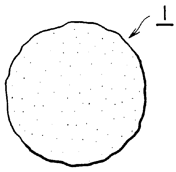
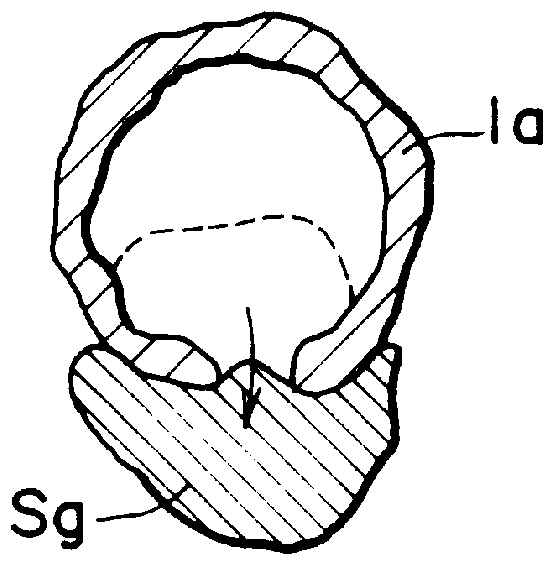
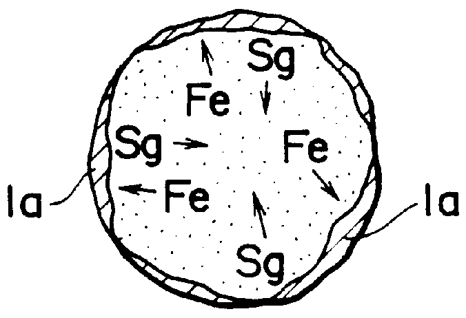
In Embodiment 4, a granular or agglomerate compact (hereinafter may be referred to as a compact) of iron oxide which contains a carbonaceous reductant is reduced through the application of heat, thereby making metallic iron. Specifically, the above-mentioned compact is rolled to be uniformly heated so as to be efficiently be reduced. In the course of this reduction, a shell composed of metallic iron is generated and grown, and slag aggregates inside the shell. This reduction is continued until substantially no iron oxide is present inside the shell. Subsequently, the compact in the form of the shell with a slag aggregate contained inside is further heated to be melted, followed by separation into molten slag and molten iron. Since the compacts are rolled, the compacts are prevented from sintering together to become a relatively large agglomerate or sinteringly adhering to a furnace wall during reduction through the application of heat.

FIG. 12 is a schematic sectional view showing an...


PUM

PropertyMeasurementUnit
temperatureaaaaaaaaaa

Abstract

A method of making metallic iron in which a compact, containing iron oxide such as iron ore or the like and a carbonaceous reductant such as coal or the like, is used as material, and the iron oxide is reduced through the application of heat, thereby making metallic iron. In the course of this reduction, a shell composed of metallic iron is generated and grown on the surface of the compact, and slag aggregates inside the shell. This reduction continues until substantially no iron oxide is present within the metallic iron shell. Subsequently, heating is further performed to melt the metallic iron and slag. Molten metallic iron and molten slag are separated one from the other, thereby obtaining metallic iron with a relatively high metallization ratio. Through the employment of an apparatus for making metallic iron of the present invention, the above-described method is efficiently carried out, and metallic iron having a high iron purity can be made continuously as well as productively not only from iron oxide having a high iron content but also from iron oxide having a relatively low iron content.

Description

The present invention relates to a method of obtaining metallic iron by subjecting iron oxides contained in iron ore or the like to reduction through the application of heat using a carbonaceous material as a reductant. More specifically, the invention relates to a method of efficiently making high purity metallic iron in which iron oxides are efficiently reduced into metallic iron while slag components including gangue and the like contained in an iron oxide source, such as iron ore, are melted and separated properly from metallic iron, and to a method and apparatus for industrially making metallic iron based on this method.A conventional method of making direct reduced iron is where iron ore or pellets which contain iron oxide are directly reduced using a reducing gas to obtain reduced iron. An example is a shaft furnace method represented by the Midrex process. In this type of method of making direct reduced iron, a reducing gas made from natural gas or the like, is forced into a...

Claims


Application Information

Patent Timeline
Patent Type & Authority Patents(United States)
IPC IPC(8): C21B13/00C21B13/10
CPCC21B13/0046C21B13/105Y10T428/2991Y02P10/134C21B13/00
Inventor NEGAMI, TAKUYAKUNII, KAZUOINABA, SHINICHISHIMIZU, MASATAKAKOBAYASHI, ISAOTAKENAKA, YOSHIMICHIMATSUMURA, TOSHIHIDEURAGAMI, AKIRAKUJIRAI, TAKASHITSUCHIYA, OSAMUSUGIYAMA, KIMIOITO, SHUZOKIKUCHI, SHOICHI
Owner KOBE STEEL LTD
Why Eureka
Try Eureka