Motor having a hollow drive shaft

a technology of hollow drive shaft and motor, which is applied in the field of hollow drive shaft for motors, can solve the problems of significant inefficiency, the need to continually dispatch spent parts of fixturing hardware or other materials from the working end of the inline device, and the inability to facilitate the rapid dispatch of spent portions of fixturing hardware associated with various tasks for which the inline device is used, so as to promote the expulsion of spent portions

Inactive Publication Date: 2008-01-17
ABEO
View PDF39 Cites 14 Cited by
  • Summary
  • Abstract
  • Description
  • Claims
  • Application Information

AI Technical Summary

Benefits of technology

[0005]It is a further object, feature, or advantage of the present invention to provide a motor having a hollow drive shaft adapted to pass through the entirety of the motor.
[0006]Yet another object, feature, or advantage of the present invention is to provide a stationary inner tube within the hollow drive shaft wherein the stationary inner tube is adapted to transfer spent portions of fixturing hardware from the working end of an inline device, through the motor and into a repository adapted to collect the spent portions.
[0007]Still a further object, feature, or advantage of the present invention is to provide a hollow rotating internal armature that has grooves to promote the expulsion of spent portions.
[0008]Another object, feature, or advantage of the present invention is to provide a fixed and / or a rotating inner hollow armature or the like adapted that may be stationary or rotate with respect to the motor.
[0009]A still further object, feature, or advantage of the present invention is to provide a motor having a hollow drive shaft adapted to expel spent portions of hardware used in conjunction with an inline device.
[0010]A further object, feature, or advantage of the present invention is to provide a plurality of grooves extending spirally along an inner circumference of the hollow inner tube or hollow drive shaft to promote transfer of spent portions through the motor into the repository.

Problems solved by technology

Although this design represents the most efficient and cost effective means of transferring rotational motion to the working end of the inline device, they do not facilitate quick dispatch of spent portions of fixturing hardware associated with various tasks for which the inline device is used.
The need to continually dispatch spent portions of fixturing hardware or other materials from the working end of an inline device represents a significant inefficiency.

Method used


Image

  • Motor having a hollow drive shaft
  • Motor having a hollow drive shaft
  • Motor having a hollow drive shaft

Examples


Embodiment Construction

[0043]Reference will now be made in detail to the presently preferred embodiments of the invention, examples of which are illustrated in the accompanying drawings.

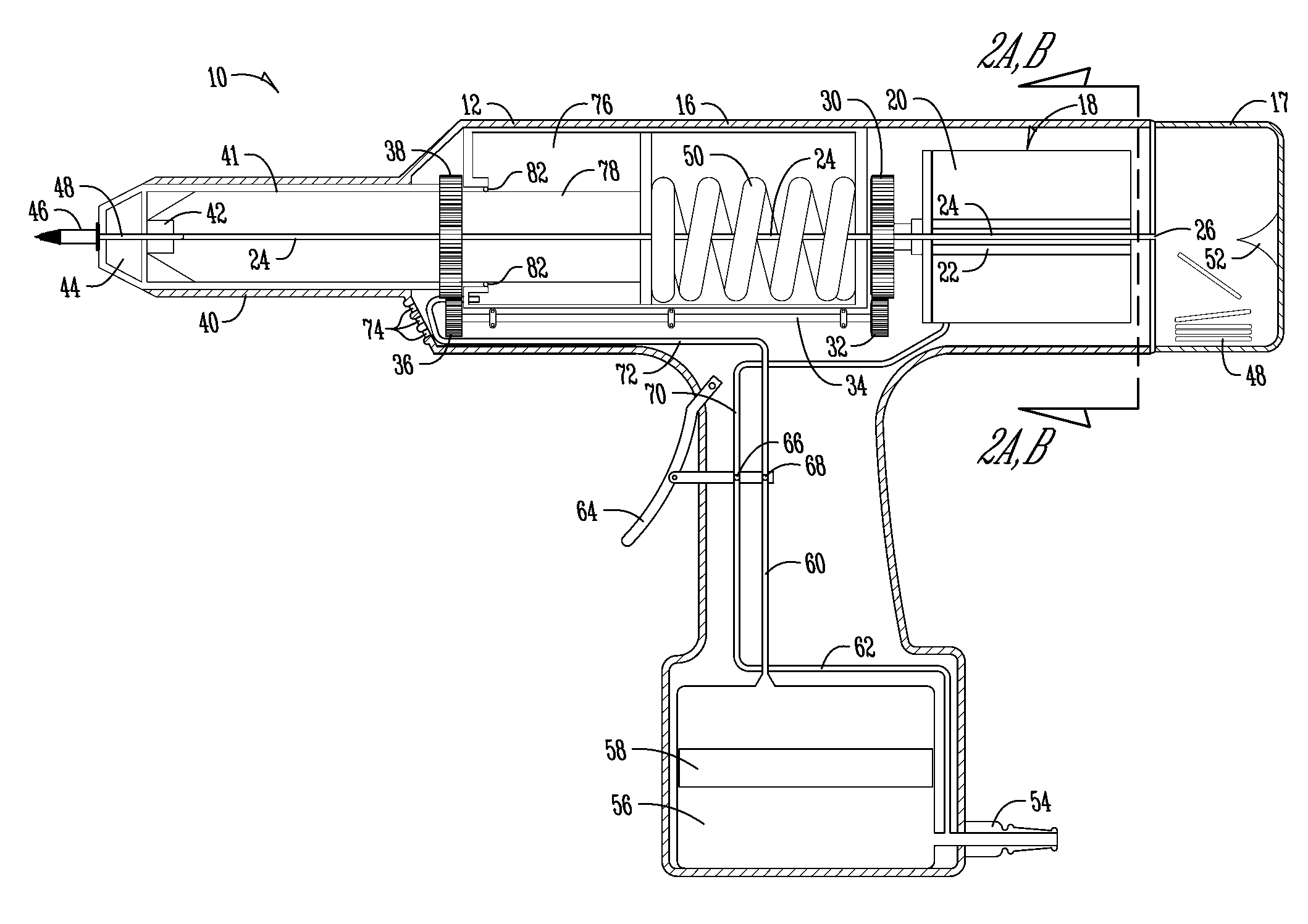
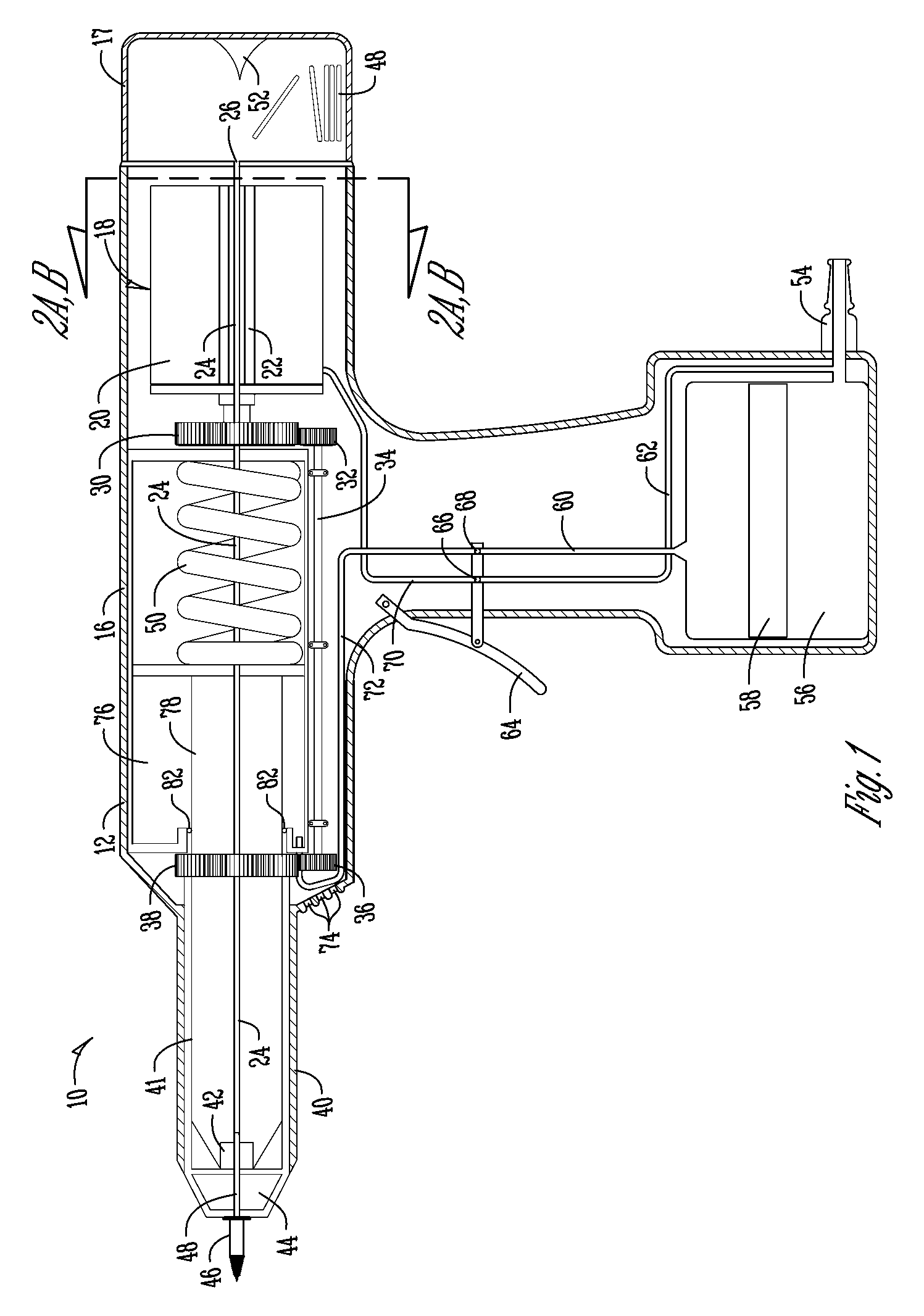
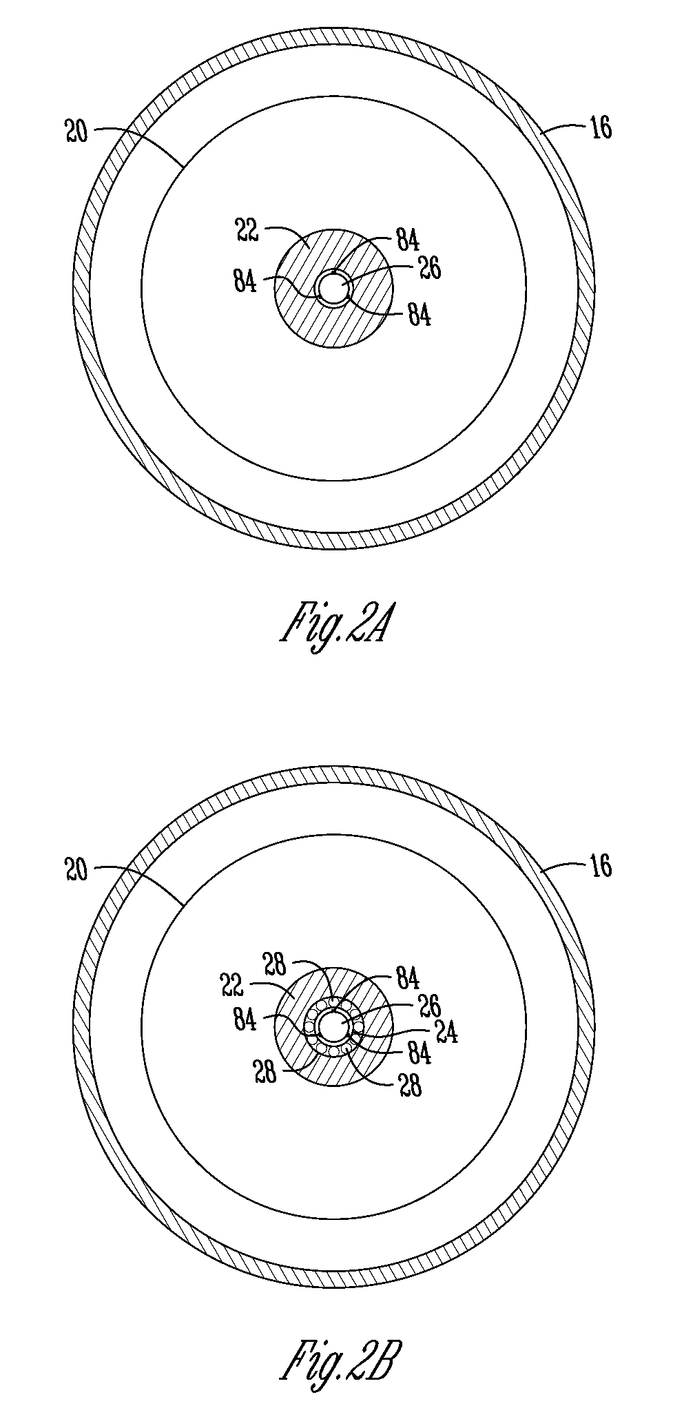
[0044]Referring generally to FIG. 1, a motor assembly 18 is described in accordance with exemplary embodiments of the present invention. The motor assembly 18 includes a hollow drive shaft 22. In a specific embodiment, the motor assembly may comprise a pneumatic motor 20 included with a riveting assembly 46. In embodiments where the riveting assembly 46 is for self-tapping rivets, the riveting assembly includes a repository 17 for receiving spent mandrels 48. In one specific embodiment, the repository 17 is co-axial with the hollow drive shaft 22 of the motor 20 to allow for direct feed of spent mandrels 48 from the self-tapping rivets through the hollow drive shaft 22 and into the repository 17. In another exemplary embodiment of the present invention, the motor 20 may have a hollow drive shaft 22 with or without grooves ...


PUM

PropertyMeasurementUnit
inner circumferenceaaaaaaaaaa
vacuumaaaaaaaaaa
movementaaaaaaaaaa

Abstract

A motor assembly for use in a inline device is disclosed. The motor assembly has a motor for operating the inline device. A hollow drive shaft passes through the motor to provide a conduit which an expendable portion of some fixturing hardware used with the inline device passes through to eject from or collect within the inline device. In another embodiment, the motor assembly is adapted for use in a tool for setting self-tapping rivets. The motor assembly has a motor having a hollow drive shaft adapted to pass through the motor and impart movement to a mandrel of the self-tapping rivet. A conduit within the hollow drive shaft is inline with the motor and is adapted to transfer the mandrel from one end of the tool, through the motor and into a repository upon detachment of the shank from the self-tapping rivet.

Description

CROSS-REFERENCE TO RELATED APPLICATIONS[0001]This application claims priority under 35 U.S.C. § 119 to provisional application Ser. No. 60 / 831,366 filed Jul. 17, 2006, herein incorporated by reference in its entirety.FIELD OF THE INVENTION[0002]The present invention generally relates to the field of motors, and more particularly to a hollow drive shaft for a motor, such as a pneumatic motor, an electric motor, or the like adapted for use in driving or operating any inline device.BACKGROUND OF THE INVENTION[0003]Traditional motors, whether pneumatic, hydraulic, hydro or electrically driven, have a central drive shaft, which is typically inline with the motor to facilitate efficient transfer of rotational motion from the motor to the central drive shaft. For example, many inline devices use a central drive shaft, coaxial with the center of the motor, to drive a working implement associated with the inline device. Although this design represents the most efficient and cost effective me...

Claims


Application Information

Patent Timeline
Patent Type & Authority Applications(United States)
IPC IPC(8): H02K7/10
CPCB21J15/043B21J15/048Y10T29/53739B21J15/26B21J15/326B21J15/105
Inventor AASGAARD, A.L. PEPPER
Owner ABEO
Why Eureka
Try Eureka