Thermally protected electrical wiring device

Inactive Publication Date: 2008-01-17
LEVITON MFG
View PDF20 Cites 29 Cited by
  • Summary
  • Abstract
  • Description
  • Claims
  • Application Information

AI Technical Summary

Benefits of technology

[0005] The present invention relates to an electrical receptacle which has at least one thermally sensitive electrically conductive element located in the receptacle and which is positioned adjacent to or in contact with a blade of an inserted p

Problems solved by technology

A situation can occur where the connection between the electrical conductors and the blades of the plug, or the connection between the blades of the plug and the blade contacts in the receptacle form a high resistance path which, in turn, can cause a high heat condition.
In another situation, a continuous high current flow may also cause a high heat condition.
This high heat condition may cause a fire.
Because the problem is at the blades of the plug or between the blades of the plug and the blade contacts in the rece

Method used


Image

  • Thermally protected electrical wiring device
  • Thermally protected electrical wiring device
  • Thermally protected electrical wiring device

Examples


first embodiment

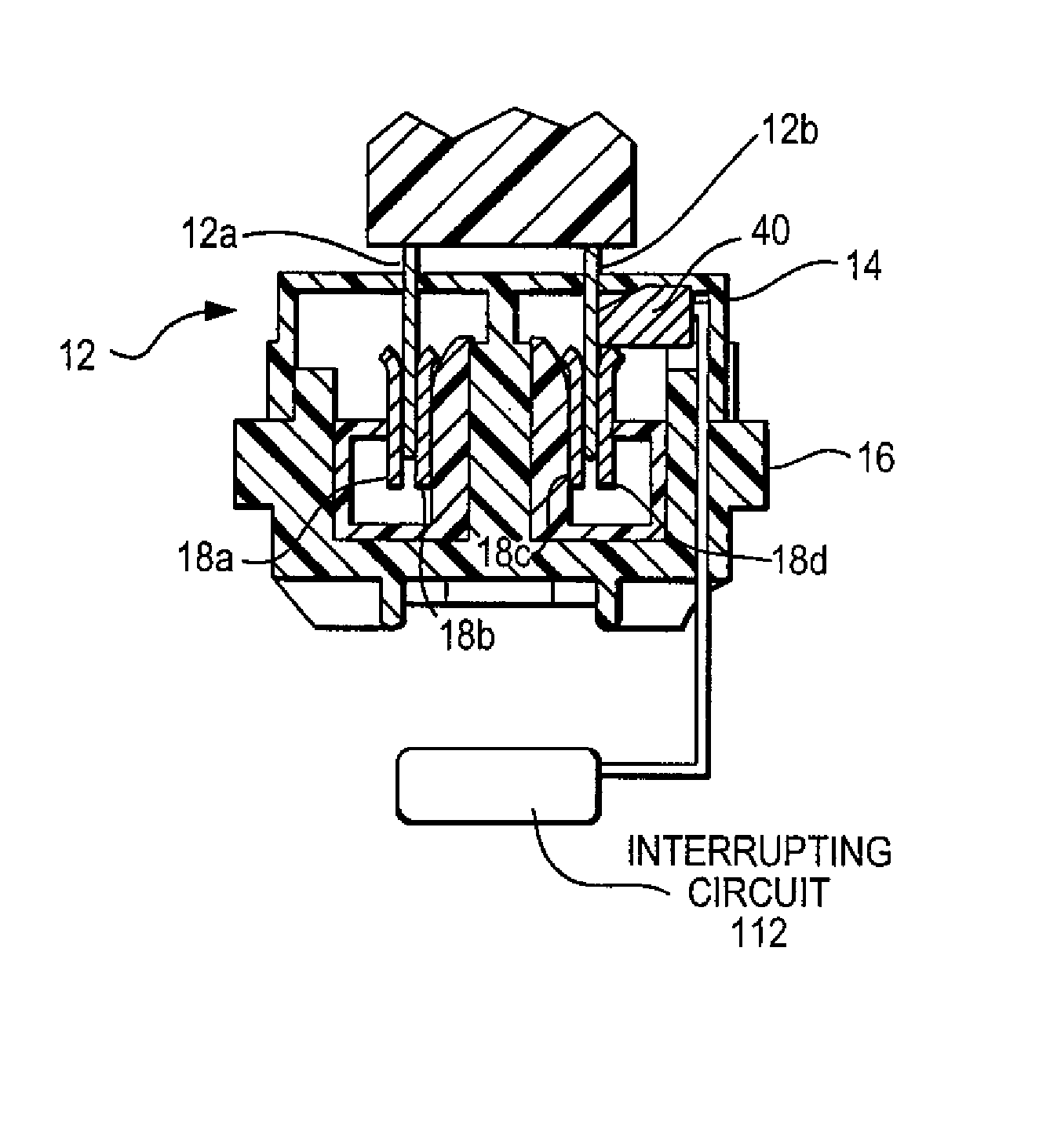
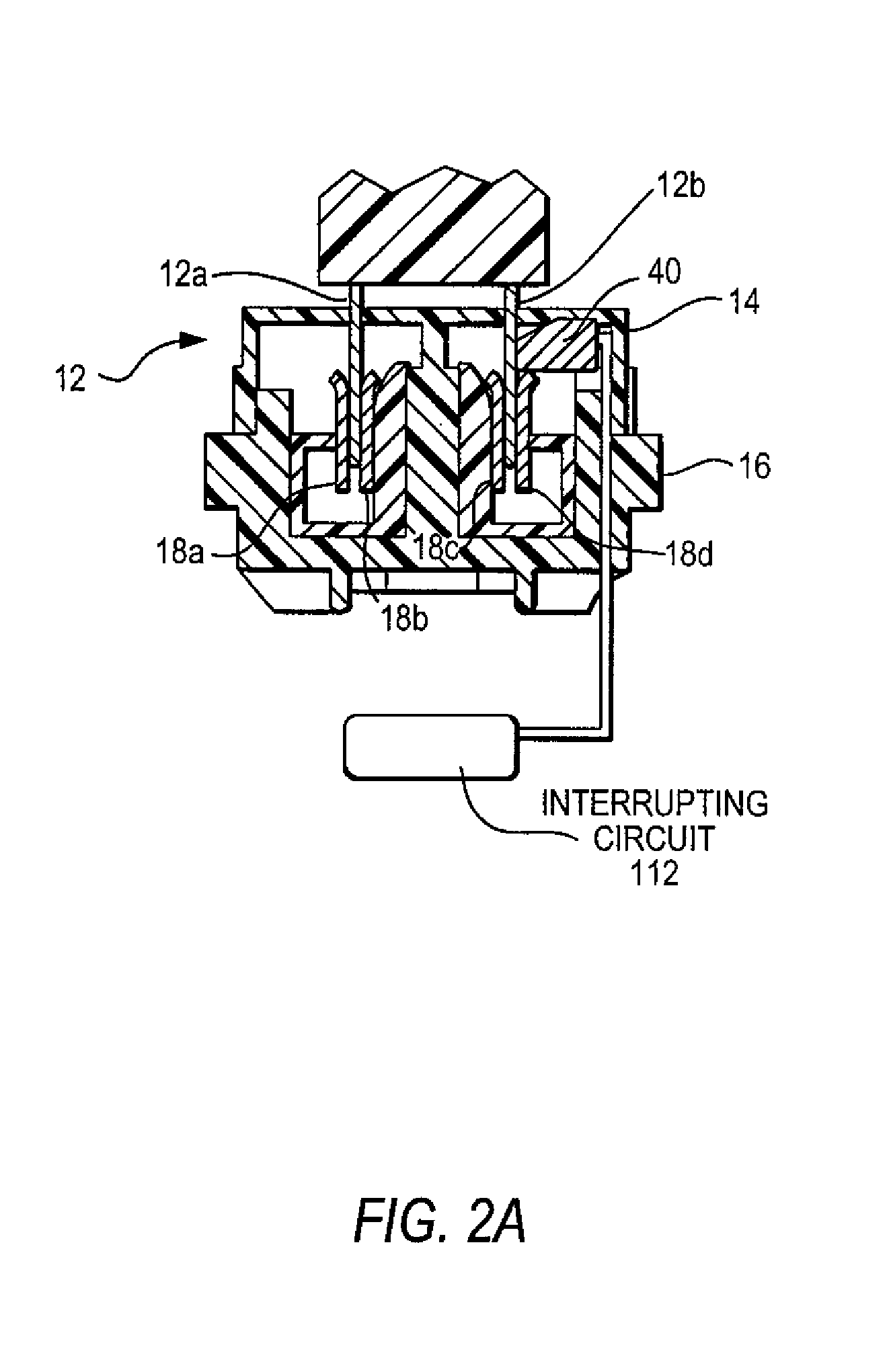
[0035] Referring to FIG. 2A, there is shown a cross-sectional view of FIG. 1 taken along Section line A-A of a first embodiment having one thermally sensitive element and a plug inserted in the receptacle. A thermally sensitive element 40 is located near one of the plug blade openings 20 just behind the receptacle face and is positioned to contact blade 12b of a plug located in the receptacle. The thermal sensitive element 40 can have a positive or negative temperature coefficient. In FIG. 2A, reference numerals 12a and 12b designate the blades of a plug, reference numerals 18a, 18b and 18c, 18d designate the two receptacle contacts which receive the blades of a plug and reference numeral 14,16 is the receptacle cover and base.

[0036] Each thermally sensitive element can made of an electrically conductive grade of thermally conductive plastics which exhibit either an increase or a decrease in resistance as its temperature rises. As such, when the temperature of the blades of a plug r...

second embodiment

[0038] Referring to FIG. 2B, there is shown a cross-sectional view of FIG. 1 taken along Section line A-A of a second embodiment having a pair of thermally sensitive elements 40. A plug is not show in this Fig. A thermally sensitive element 40 is located near each one of the plug blade openings 20 just behind the receptacle face and the two thermally sensitive elements 40 are positioned to contact the two blades of a plug located in the receptacle. Thermally sensitive elements 40 can have a positive or negative temperature coefficient. As with FIG. 2A, an interrupting circuit 112 is connected to the elements 40 to interrupt the flow of current through the receptacle when a high heat condition is detected by one or both of the thermally sensitive elements.

third embodiment

[0039] Referring to FIG. 3A, there is shown a cross-sectional view of FIG. 1 taken along Section line A-A of a third embodiment having one thermally sensitive element located to sense the heat of one blade receiving contact in the receptacle positioned to receive a blade of an inserted plug. The plug is not shown. The thermally sensitive element 110a is located to contact one of the blade receiving contacts 108a, 108b located in the body of the receptacle behind plug blade openings 20 and behind the receptacle face. Thermal sensitive element 110a can have either a positive or a negative temperature coefficient. As with FIG. 2A, an interrupting circuit 112 is connected to the elements 110a to interrupt the flow of current through the receptacle when a high heat condition is detected by the thermally sensitive element.


PUM


Abstract

A receptacle having at least one thermally sensitive electrically conductive element made of, for example, a thermally conductive plastic which either increases or decreases its conductivity when subjected to an increase in temperature. The thermally sensitive element is positioned within the housing of the receptacle such that it makes contact with a blade of an inserted plug or a blade receiving contact in the receptacle. By contacting at least one blade of a plug, or the blade receiving contact in the receptacle, the thermally sensitive element is positioned to detect a temperature rise. A circuit interrupting device located within the receptacle and coupled to the thermally sensitive element is configured to cause electrical discontinuity between the line and load of the receptacle upon the detection of a high heat condition by the thermally conductive element.

Description

[0001] This application claims priority pursuant to 35 U.S.C. 119(e) from U.S. Provisional Application having Application No. 60 / 803,328 filed May 26, 2006.FIELD OF THE INVENTION [0002] The present invention relates generally to electrical wiring devices, and, more particularly, to electrical receptacles which can provide protection for an over heat condition. BACKGROUND OF THE INVENTION [0003] An electrical plug, when inserted into a wall mounted receptacle, will connect an electrical appliance to a source of AC current. A situation can occur where the connection between the electrical conductors and the blades of the plug, or the connection between the blades of the plug and the blade contacts in the receptacle form a high resistance path which, in turn, can cause a high heat condition. In another situation, a continuous high current flow may also cause a high heat condition. This high heat condition may cause a fire. Because the problem is at the blades of the plug or between the...

Claims


Application Information

Patent Timeline
IPC IPC(8): H01H37/00
CPCH01H77/04
Inventor KADAR, PAULODDSEN, DENNIS
Owner LEVITON MFG
Why Eureka
Try Eureka