Method of making, apparatus, and article of manufacture for an ultracapacitor electrode termination contact interface

Inactive Publication Date: 2008-01-17
TESLA INC
View PDF9 Cites 17 Cited by
  • Summary
  • Abstract
  • Description
  • Claims
  • Application Information

AI Technical Summary

Problems solved by technology

Such improved double layer capacitors need to deliver large amounts of useful energy at a very high power output and energy density ratings within a relatively short period of time.
However, all real capacitors have some amount of ESR.
Hence, a real-world challenge for capacitor designers is minimizing ESR.
Capacitor designs that appear optimally functional in theory, can fail when manufac

Method used


Image

  • Method of making, apparatus, and article of manufacture for an ultracapacitor electrode termination contact interface
  • Method of making, apparatus, and article of manufacture for an ultracapacitor electrode termination contact interface
  • Method of making, apparatus, and article of manufacture for an ultracapacitor electrode termination contact interface

Examples


Embodiment Construction

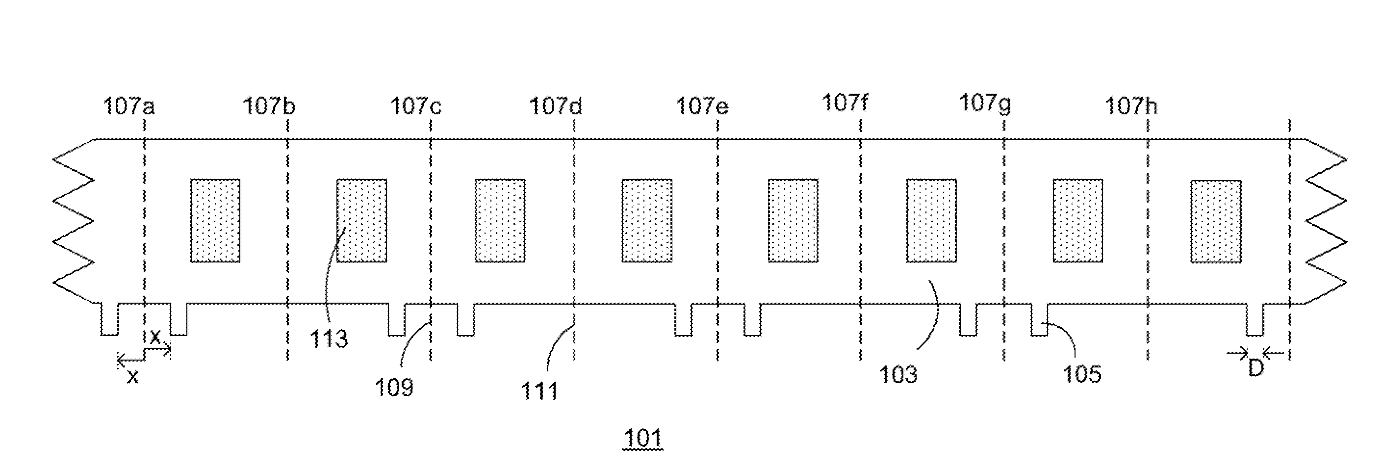
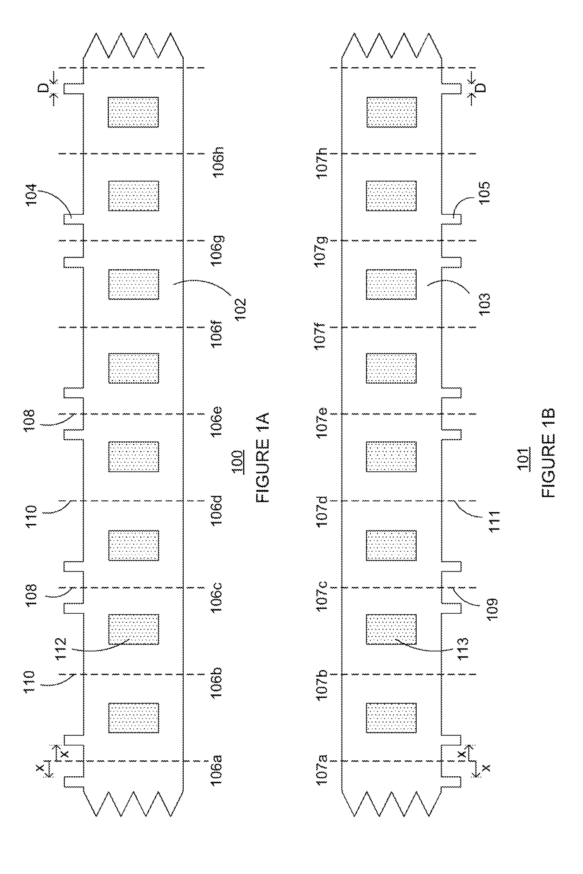
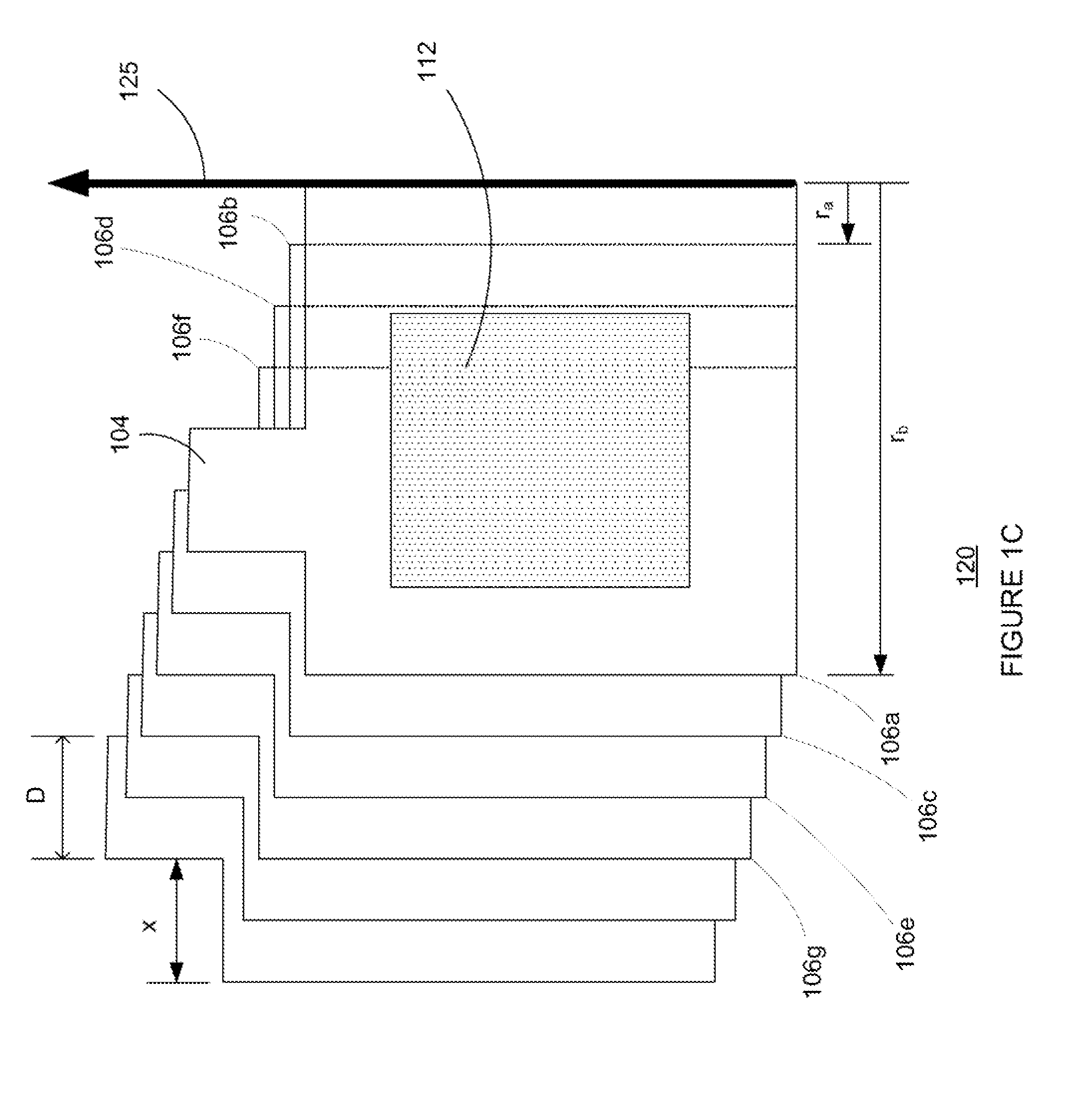
[0032]FIG. 1A illustrates a front plan view of an unfolded electrode termination foil 100 showing, a plurality of current collecting tab portions 104 oriented in a positive vertical direction. In one illustrative exemplary embodiment the unfolded electrode termination foil 100 of the present teachings comprises a first electrode foil 102, a plurality of active carbon deposits 112, the plurality of current collecting tab portions 104, and a plurality of fold zones bounded by fold lines 106a-h. The fold lines 106a-h comprise a plurality of fold lines including a plurality of fold zone inner radius folds 110 and further bounded by a plurality of fold zone outer radius folds 108. The plurality of current collecting tab portions 104 have a tab width of “D”, as shown in FIG. 1A. A distance “x” measured laterally away from each of the plurality of fold zone outer radius folds 108 marks a position for each of the plurality of current collecting tab portions 104. Using the techniques describ...


PUM


Abstract

An ultracapacitor electrode termination contact interface adapted for use in an energy storage device is disclosed. The disclosed apparatus and article of manufacture function to lower equivalent series resistance of the ultracapacitor electrode termination contact interface. In one embodiment of the present teachings, an ultracapacitor electrode termination contact interface, adapted to increase reliability and manufacturing yield of such devices is disclosed.

Description

BACKGROUND [0001]1. Field[0002]The disclosed method of making, apparatus, and article of manufacture relates generally to high performance energy storage devices, and particularly to increasing ultracapacitor electrode interface efficiency and lowering equivalent series resistance of such interfaces.[0003]2. Related Art[0004]Double layer capacitors, also referred to as electrochemical double layer capacitors, are energy storage devices that are able to store more energy per unit weight and unit volume than traditional capacitors. Additionally, they can typically deliver the stored energy at a higher power rating than rechargeable batteries.[0005]Double layer capacitors consist of two porous electrodes that are isolated from electrical contact by a porous separator. Both the separator and the electrodes are impregnated with an electrolytic solution. This allows ionic current to flow between the electrodes through the separator at the same time that the separator prevents an electrica...

Claims


Application Information

Patent Timeline
IPC IPC(8): H01G9/00
CPCH01G9/016H01G11/52H01G11/66Y02E60/13H01G11/84H01G13/006H01G11/74
Inventor MILLER, JOHN
Owner TESLA INC
Why Eureka
Try Eureka