Illumination device and lens of illumination device
Active Publication Date: 2008-01-17
ENPLAS CORP
View PDF3 Cites 94 Cited by
Summary
Abstract
Description
Claims
Application Information
AI Technical Summary
This helps you quickly interpret patents by identifying the three key elements:
Problems solved by technology
Method used
Benefits of technology
Benefits of technology
[0021] Lens configuration employed in the present invention avoids the rays from having travelling directions crossed each other in a region which can be substantially illuminated (i.e. a three-dimensional region through which the rays proceed from the light control emission face to the surface-to-be-illuminated).
[0024] The present invention is able to satisfy such requirement. That is, the region-to-be-illuminated avoids from having an illuminance reduction which could appear in an area deviated from the frontal direction, resulting in uniformalized illuminance over surface-to-be-illuminated.
Problems solved by technology
However, if illumination device 101 shown in FIG. 21 is applied to an image pickup device, a problem arises.
Method used
Image
Click on the blue label to locate the original text in one second.
Reading with bidirectional positioning of images and text.
Examples
first embodiment
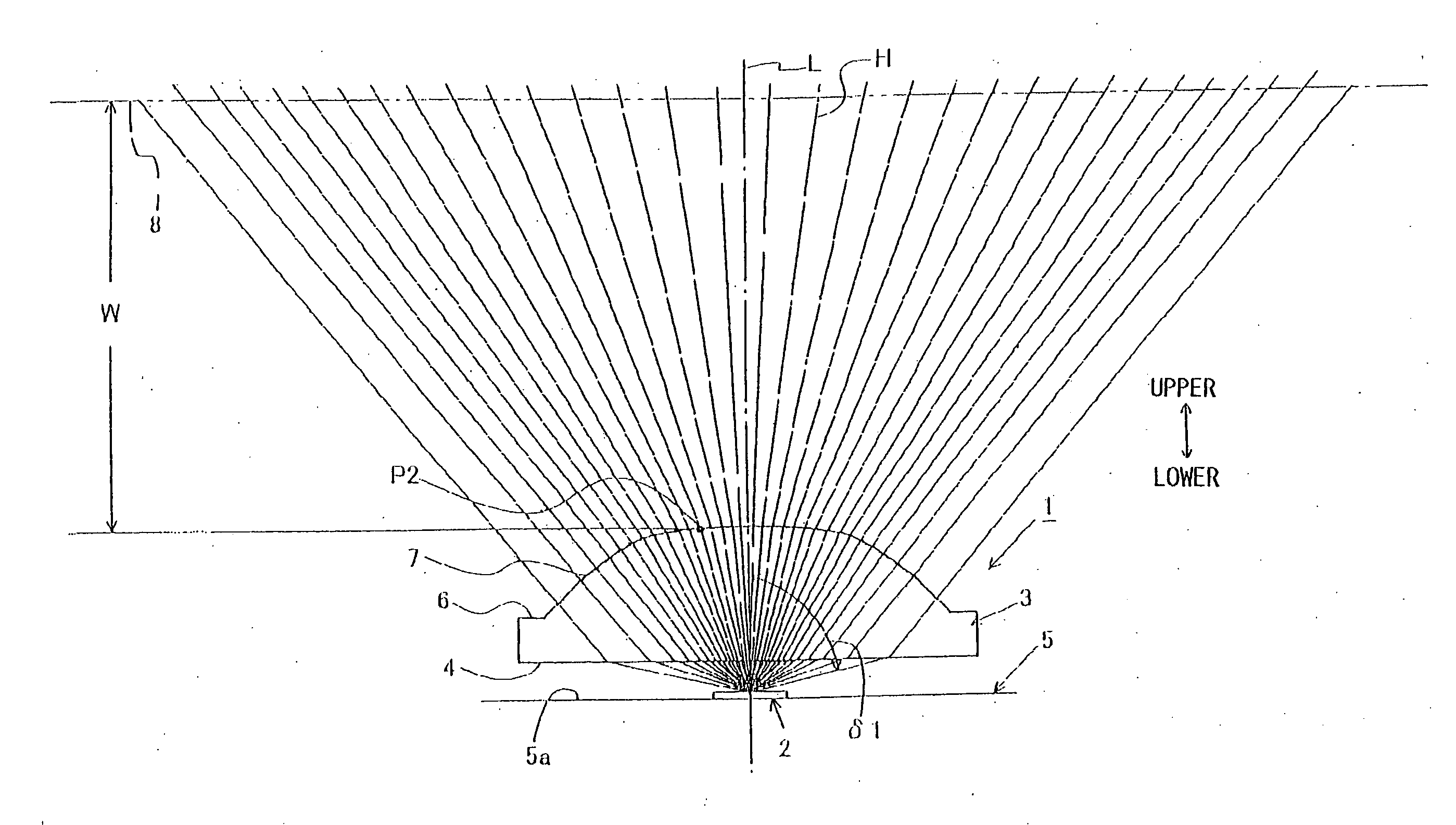
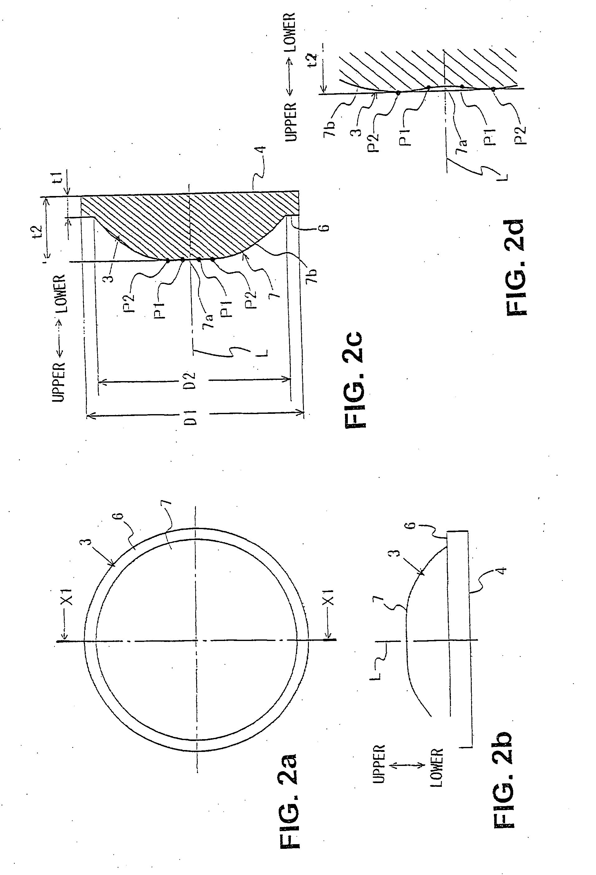
[0059]FIG. 1 is a diagramic view of an illumination device in accordance with a first embodiment of the present invention. Referring to FIG. 1, illumination device 1 outputs light (rays) H from light emitting element (point-like light source) 2 via lens 3, illuminating surface-to-be-illuminated 8. It is noted that “surface-to-be-illuminated 8” is a surface set in a region which can be illuminated by illumination device 1. For instance, if illumination device 1 is a strobo-illuminator for camera, the surface is set in the greatest region which can be illuminated by the strobo-illuminator, namely, “an imaginary surface set at a position located within an irradiation distance in which strobo illumination is allowed to function substantially”. Light emitting element 2 is a point-like light source, employing a LED (not shown) sealed by resin. It is noted that resin for sealing may contain fluorescent substance as required.
[0060] Lens 3 is configured as illustrated in FIGS. 2a to 2d, bei...
second embodiment
[0102]FIG. 10 is a diagramic view of an illumination device 21 in accordance with a second embodiment of the present invention. As shown in FIG. 10, illumination device 21 outputs light H from light emitting element 2 via lens 23 in generally the same way as the first embodiment. However, lens 23 employed in illumination device 21 is configured differently as compared with lens 3 employed in illumination device 1 of the first embodiment.
[0103]FIG. 11a is a plan view of a lens employed in the illumination device shown in FIG. 10 and FIG. 11b is a side view of the same lens. FIG. 11c is a cross section view along line X3-X3 in FIG. 11a. FIG. 11d is a cross section view along line X2-X2 in FIG. 11a and FIG. 11e is a partially enlarged view of FIG. 11d.
[0104] First, lens 3 has a shape like a square in plan as shown in FIG. 10a, being provided with a lower face (incidence face) 4 which is directed to light emitting element 2 and extends parallel with a surface (reference plane) 5a on w...
third embodiment
[0152]FIG. 14 is a diagramic view of illumination device 41 in accordance with a third embodiment of the present invention. Illumination device 41 has lens 43 irradiation characteristics of which are different those of lens 23 employed in the second embodiment (See FIGS. 15 and 12).
[0153] Thus lens 43 has light control emission face 47 different from light control emission face 27 of lens 23. Except for this difference, the third embodiment is the same as illumination device 21 of the second embodiment. Therefore, common elements are denoted by the same reference characters and description overlapping that of the second embodiment is omitted.
[0154] Lens 43 employed in this embodiment is structured so that region-to-be-illuminated 50 has a higher illuminance in vicinity-of-periphery-portion 51 as compared with a center portion of region-to-be-illuminated 50, as shown in FIG. 15. Features of lens 43 are described below by comparing with lens 23.
[0155] Lens 43 may be made of the sam...
PUM
Abstract
Provided are an illumination device and a lens employed in the device for controlling light travelling direction, the device being capable of illuminating brightly and uniformly a certain limited region (region-to-be-illuminated) corresponding to an object such as subject for photography. The illumination device emits light H coming from a light emitting element (point-like light source) employing a LED as a light emitting source via the lens. A light control emission face of the lens emits light (rays), which is included in light H introduced into the lens through an incidence face thereof and travelling within the lens to the light control emission face without undergoing inner-reflection at any surface of the light control emission face, as illumination light. The light control emission face is configured so that no set of rays included in the illumination light make any crossover at least before reaching a region-to-be-illuminated and rays within a direction range near to a direction of optical axis L have lower light flux density as compared with that in the outside of the direction range.
Description
BACKGROUND [0001] 1. Field of Inventions [0002] The present invention relates to an illumination device for illuminating a certain region-to-be-illuminated with light emitted from a point-like light source and a lens employed in he illumination device, being applied to an illumination devices for electronic-flash-illumination in for portable phones, digital cameras, video cameras or others, or to illumination devices for book-reading illuminators, map illuminators or the likes, and to lenses employed in the devices. [0003] In general, the present invention can be broadly applied to illumination devices which are used for supplying illumination light to a certain limited region-to-be-illuminated like a region corresponding to an object such as subject for photography, and to lenses employed in them for controlling light traveling directions. [0004] 2. Related Arts [0005] It is known well to have image-pickup-devices such as portable phones, digital cameras or video cameras be equippe...
Claims
Application Information
Patent Timeline
Application Date:The date an application was filed.
Publication Date:The date a patent or application was officially published.
First Publication Date:The earliest publication date of a patent with the same application number.
Issue Date:Publication date of the patent grant document.
PCT Entry Date:The Entry date of PCT National Phase.
Estimated Expiry Date:The statutory expiry date of a patent right according to the Patent Law, and it is the longest term of protection that the patent right can achieve without the termination of the patent right due to other reasons(Term extension factor has been taken into account ).
Invalid Date:Actual expiry date is based on effective date or publication date of legal transaction data of invalid patent.
Patent Type & AuthorityApplications(United States)

