

Display apparatus for vehicle and display method
a technology for display apparatus and vehicle, applied in the direction of instruments, navigation instruments, optical elements, etc., can solve the problem of difficulty in co-occurrence of the depth perception position of presented information with the real spatial location
- Summary
- Abstract
- Description
- Claims
- Application Information
AI Technical Summary
Problems solved by technology
Method used
Image

Examples
first embodiment
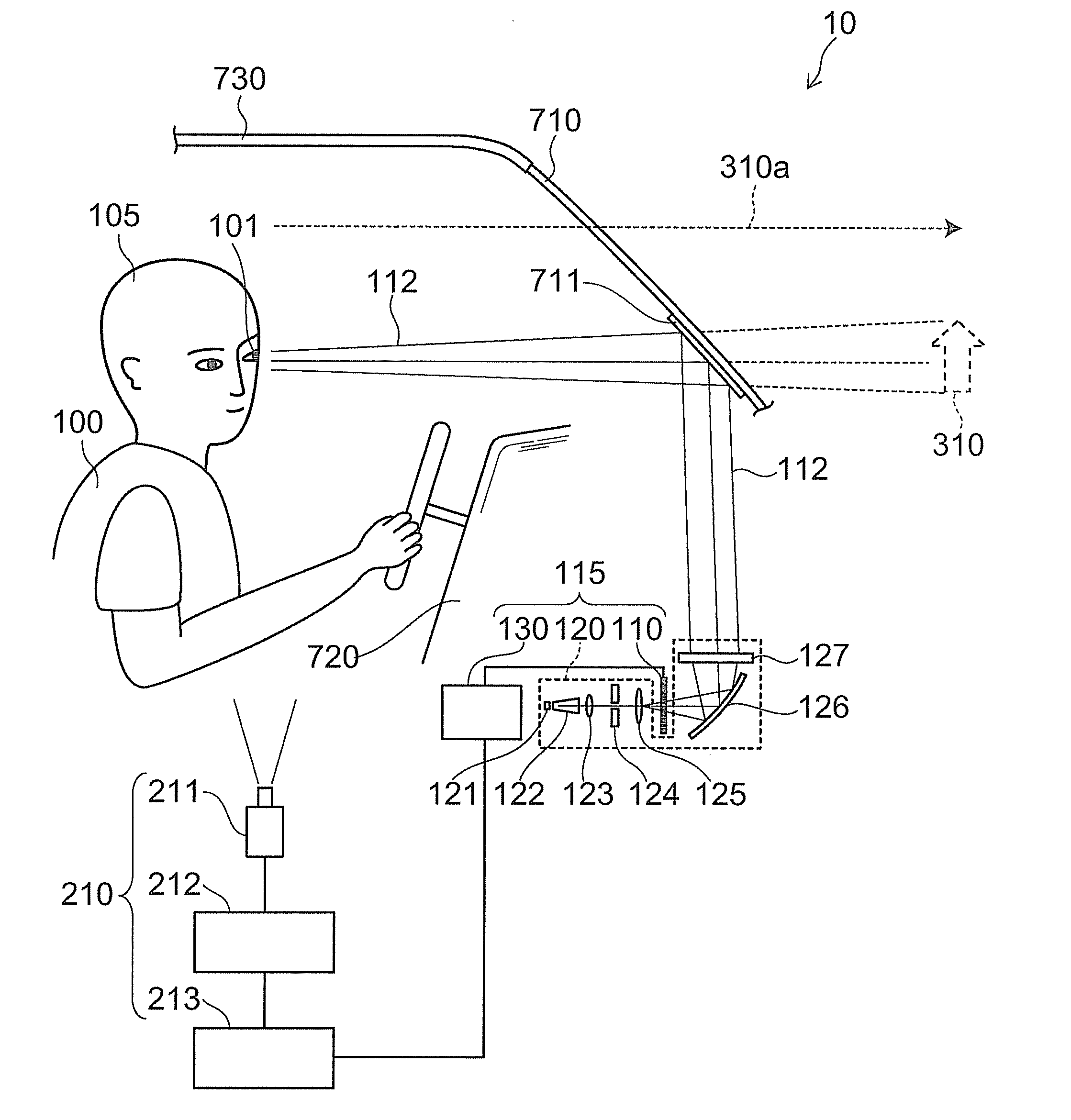
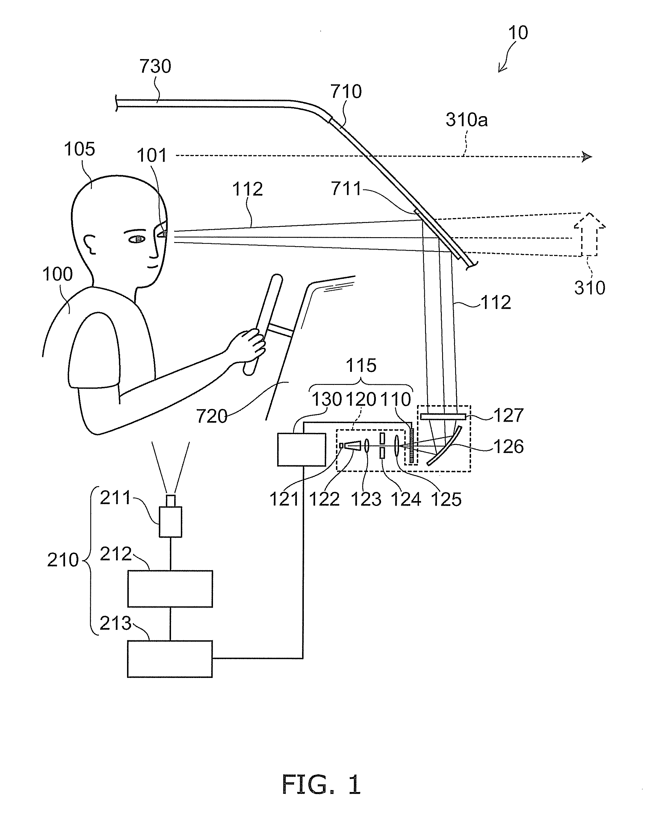
[0028]FIG. 1 is a schematic view illustrating the configuration of a display apparatus for vehicle according to a first embodiment of the invention.
[0029]As shown in FIG. 1, the display apparatus for vehicle 10 according to the first embodiment of the invention includes an image projector 115 configured to project a light flux 112 for projecting an image containing a display object toward one eye 101 of an image viewer 100, and a position detector 210 configured to detect the one eye 101 of the image viewer 100. Thus, the light flux 112 includes the image having a display object.
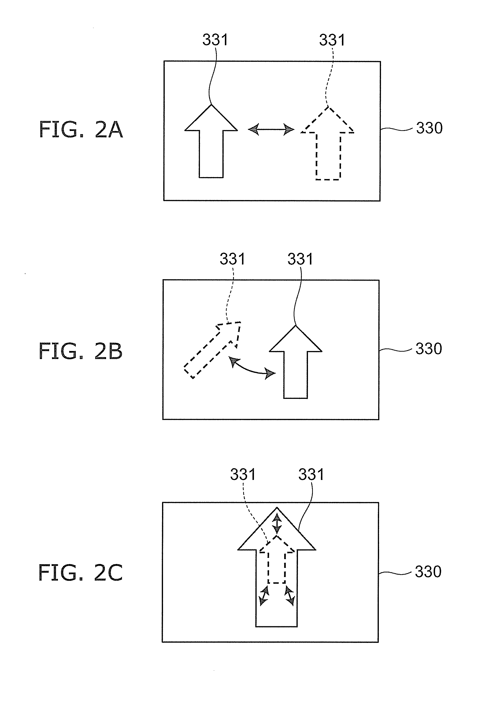
[0030]The display object is provided in the image presented by the display apparatus for vehicle 10 to the image viewer 100, and for example, is a display content such as an arrow representing traveling direction, speed, attention, or warning, with regard to driving information of a moving object 730 on which the display apparatus for vehicle 10 is mounted.
[0031]As illustrated in the figure, the display appa...
second embodiment
[0136]A display apparatus for vehicle 20 according to a second embodiment of the invention has the same configuration as that of the display apparatus for vehicle 10 illustrated in FIG. 1, and thus the configuration description is omitted. The display apparatus for vehicle 20 according to this embodiment shows a further advanced operation in addition to the operation of the display apparatus for vehicle 10 of the first embodiment.
[0137]FIG. 12 is a schematic view illustrating the operation of the display apparatus for vehicle according to the second embodiment of the invention.
[0138]As shown in FIG. 12, the depth presenting target position P02 of the image is continuously changed in the display apparatus for vehicle 20 according to the second embodiment of the invention. For example, the depth presenting target position P02 is changed from the position P4 farthest from the image viewer 100 toward the nearest position P1 via the position P3 and the position P2, and may be changed in ...
third embodiment
[0143]FIG. 13 is a schematic view illustrating the configuration of a display apparatus for vehicle according to a third embodiment of the invention.
[0144]As shown in FIG. 13, the display apparatus for vehicle 30 according to the third embodiment of the invention further includes a controller 250 configured to adjust at least one of a projected area 114a and a projected position 114 of the light flux 112 by controlling the image projector 115 on the basis of the position of the one eye 101 of the image viewer 100 detected by the position detector 210 in addition to the configuration of the display apparatuses for vehicle 10, 20 according to the first and second embodiments.
[0145]In the specific example, the controller 250 illustratively controls the projected position 114 by controlling a driving section 126a connected to the mirror 126 forming part of the projector 120 to control the angle of the mirror 126.
[0146]The controller 250 can illustratively control the projected area 114a...
PUM
 Abstract
Description
Claims
Application Information