Optical scanning apparatus and image forming apparatus using the same

a scanning apparatus and optical technology, applied in the field of optical scanning apparatus, can solve the problems of increasing cost factors, high working cost, and considerable load on the laser itself, and achieve the effect of reducing non-uniform distribution and improving the stability of light quantity

Inactive Publication Date: 2006-06-27
CANON KK
View PDF18 Cites 54 Cited by
  • Summary
  • Abstract
  • Description
  • Claims
  • Application Information

AI Technical Summary

Benefits of technology

[0019]Another object of the present invention is to provide an optical scanning apparatus in which light quantity distribution nonuniformity due to absorption in an optical resin is reduced to ensure image density uniformity.
[0021]That is, according to the present invention, in the scanning optical system in which the wavelength of the light source is 500 nm or less and a reflecting mirror is provided, a suitable metallic material for the reflecting mirror is selected to increase the absolute reflectance and to improve the wavelength dependent characteristic and the angle characteristic of the reflectance.
[0024]That is, according to the present invention, in the scanning optical system in which the wavelength of the light source is 500 nm or less and at least one plastic lens is provided, a restriction is put on the selection of the thickness of the plastic lens to reduce nonuniformity of distribution of the quantity of light due to internal absorption in the optical resin, thus guaranteeing image density uniformity.
[0025]Also, an optical component having a characteristic similar to the inverse of the wavelength characteristic of transmittance of the plastic lens is provided to improve the stability of quantity of light even when the wavelength of the light source is changed in the operational environment.

Problems solved by technology

In recent years, as such lenses, low-cost plastic lenses capable of being freely shaped to correct aberrations have ordinarily been used since working of glass lenses is difficult to perform and the working cost is high.
In such a situation, the load on the laser itself is considerably heavy and there are cost-increasing factors, e.g., an increase in the number of collimator lenses for suitably correcting aberrations.
Moreover, because of the angle dependence of the reflectance, the uniformity of image density between the scanning center and scanning end is far from sufficient for formation of a high-quality image.
In the case of use with a light source of a short wavelength in the vicinity of 400 nm, however, the reduction in transmittance due to internal absorption is not negligible.
Also, since the ray passage distance in the plastic lens changes with respect to the image size, deterioration in image quality due to light quantity distribution nonuniformity at the position on the scanned image surface is more considerable than the reduction in absolute quantity of light.
In a case where a plastic lens is used in a short wavelength range in the vicinity of 400 nm, there is a problem of image density nonuniformity which, as can be understood from FIG. 15, results from variation in the quantity of light on the scanned surface due to the wavelength dependence of the transmittance.

Method used


Image

  • Optical scanning apparatus and image forming apparatus using the same
  • Optical scanning apparatus and image forming apparatus using the same
  • Optical scanning apparatus and image forming apparatus using the same

Examples


first embodiment

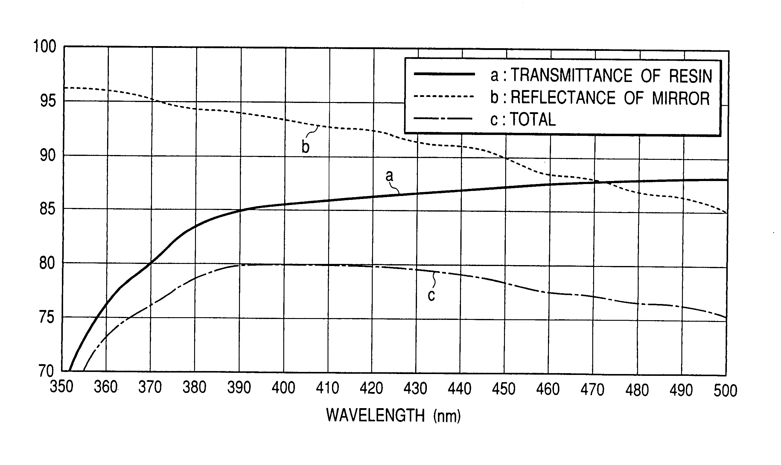
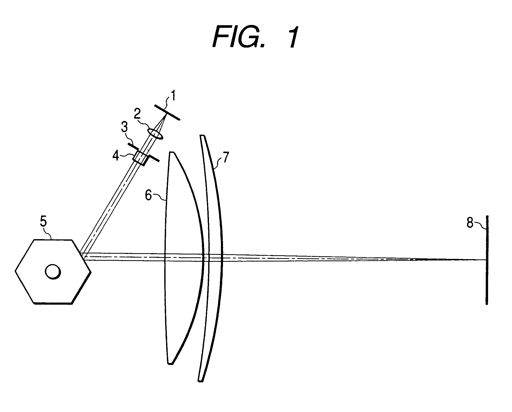
[0043]FIG. 1 is a schematic cross-sectional view of an essential portion of an optical scanning apparatus in which features of the present invention are best shown. Divergent rays of light from a semiconductor laser 1, i.e., a light source, are converted into an approximately parallel light beam by a collimator lens 2 and the diameter of the light flux is reduced by an aperture 3 to obtain a desired spot diameter. The semiconductor laser 1 used in this embodiment is a gallium nitride semiconductor laser having an oscillation wavelength of 408 nm. A rotary polygon mirror 5 is provided which reflects the light beam from the light source so that the light beam travels to a surface 8 to be scanned. The reflected light beam from the polygon mirror 5 passes through scanning lenses 6 and 7 to form a small spot at any point in the entire scanning area. It is required that the scanning lenses 6 and 7 have an fθ characteristic such that the light beam deflected at a constant angular velocity ...

second embodiment

[0062]FIG. 4 is a schematic cross-sectional view along a sub-scanning direction of an essential portion of an optical scanning apparatus which represents a second embodiment of the present invention. The incidence optical system (not shown) from the semiconductor laser to the polygon mirror is the same as that in the first embodiment. In many cases of use of optical scanning apparatuses in image forming apparatuses, the scanning light beam is bent in the sub-scanning direction for some reason relating to the layout of units of the image forming apparatus. In this embodiment, the light beam moved for scanning along a horizontal direction passes through scanning lenses 6 and 7 and is perpendicularly bent one time by a bending mirror 9 to travel to a photosensitive drum 10. Ordinarily, a mirror used like the bending mirror 9 has a metallic film vapor-deposited on a surface of a glass base member. In this embodiment, aluminum is vapor-deposited as described above to achieve the effect o...

third embodiment

[0069]FIG. 6 is a perspective view of an optical scanning apparatus which represents a third embodiment of the present invention. This embodiment differs from the first or second embodiment in that a scan-imaging mirror 11 is used instead of the scanning lens 7. As scan-imaging mirror 11, a cylindrical mirror, a spherical mirror, or a lens with a freely curved surface, recently put to use with improvements in plastic forming techniques, may be used. The advantage of use of the scan-imaging mirror 11 in the scan-imaging system resides in its having both an imaging lens function and a bending mirror function. Therefore, it is possible to remove the bending mirror described with respect to the second embodiment. That is, a reduction in manufacturing cost can be achieved by reducing the number of components.

[0070]The scanning lens 6 used in this embodiment may be made of either glass or a plastic. However, if the lens is made of a plastic, it is preferred that the lens satisfy condition...


PUM


Abstract

A scanning optical system using a short-wavelength light of 500 nm or less uses a reflecting mirror having a higher absolute reflectivity and having reduced wavelength and angle dependences. Divergent ray of light emitted from a semiconductor laser is converted into an approximately parallel light beam by a collimator lens and the diameter of the light flux is reduced by an aperture before travel to a polygon mirror. The light beam from the polygon mirror passes through scanning lenses to form a small spot at any point in the entire scanning area. The semiconductor laser is a gallium nitride semiconductor laser having an oscillation wavelength of 408 nm. The polygon mirror has such a characteristic that, if the complex refractive index N of a metallic film contributing to a reflection characteristic of the reflecting mirror is defined as N(λ)=n(λ)−ik(λ), then k(λ)>√{square root over ((−n(λ)2+18n(λ)−1))}{square root over ((−n(λ)2+18n(λ)−1))} is satisfied.

Description

[0001]This application is a division of application Ser. No. 10 / 041,463, filed Jan. 10, 2002 now U.S. Pat. No. 6,760,138.BACKGROUND OF THE INVENTION[0002]1. Field of the Invention[0003]The present invention relates to an optical scanning apparatus used in an image forming apparatus such as a laser printer, a digital copying machine, or a multifunction printer.[0004]2. Related Background Art[0005]Ordinarily, optical scanning apparatuses for use in these kinds of image forming apparatus operate in such a manner that a beam of light from a laser light source is deflected by a polygon mirror and travels through an imaging lens system to thereby form an imaging light spot on a surface to be scanned.[0006]There are many cases where a semiconductor laser or the like is used as a laser light source in a manner described below. Divergent rays of light emitted from a laser light source are converted into an approximately parallel light beam by a collimator lens and the light beam is shaped by...

Claims


Application Information

Patent Timeline
Patent Type & Authority Patents(United States)
IPC IPC(8): G02B26/08B41J2/44G02B5/08G02B5/09G02B26/10G02B26/12
CPCG02B5/0808G02B5/0858G02B26/125G02B26/12G02B5/09
Inventor SHIMOMURA, HIDEKAZU
Owner CANON KK
Why Eureka
Try Eureka