Microscope device and image processing method

a microscope and image processing technology, applied in the field of microscope devices and image processing methods, can solve the problems of hardly observing objects in real time, hardly obtaining good super-resolution images, and taking time for computer demodulation, etc., and achieve the effect of high speed

Active Publication Date: 2009-09-10
NIKON CORP
View PDF1 Cites 53 Cited by
  • Summary
  • Abstract
  • Description
  • Claims
  • Application Information

AI Technical Summary

Benefits of technology

[0025]Accordingly, the invention can provide the microscope apparatus that can produce the information on the super-resolution image at high speed and the image processing method in which the accurate image can be obtained with the microscope apparatus.

Problems solved by technology

However, the computing demodulation takes time because of complicated arithmetic processing, and the observation object is hardly observed in real time.
However, because demodulation accuracy depends on shape accuracy and arrangement accuracy of the spatial modulation element, a good super-resolution image is hardly obtained.
However, unfortunately an observation field is extremely narrowed because a pupil of the optical system relating to the modulation and a pupil of the optical system relating to the demodulation cannot be conjugated.

Method used


Image

  • Microscope device and image processing method
  • Microscope device and image processing method
  • Microscope device and image processing method

Examples


first embodiment

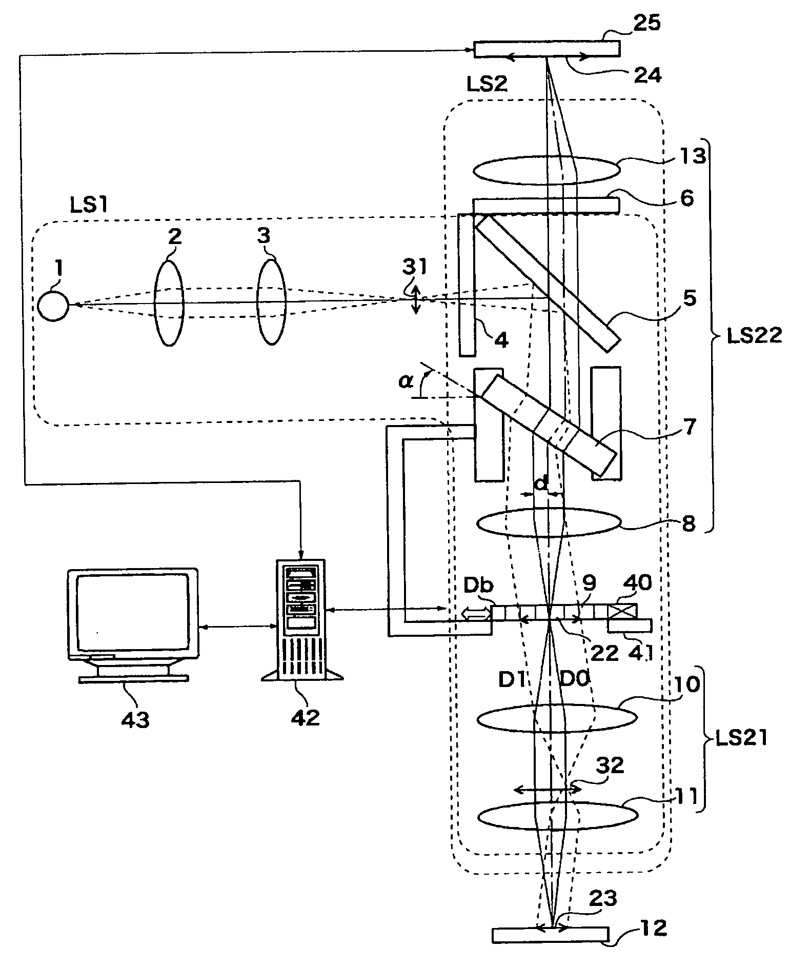
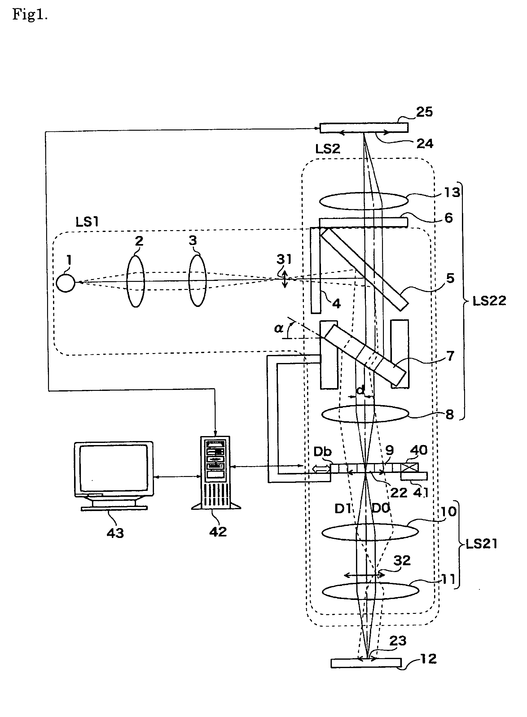
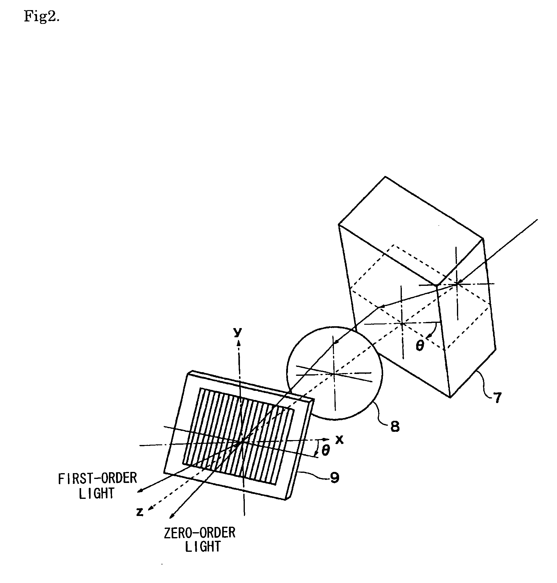
[0083]Exemplary embodiments of the invention will be described with reference to the drawings. FIG. 1 is a view showing an outline of an optical system of a microscope apparatus according to the invention. The microscope apparatus includes a light source 1, a collector lens 2, a collimator lens 3, an exciter filter 4, a dichroic mirror 5, a barrier filter 6, a parallel-plate glass 7 which is of an optical path moving optical system, a lens 8 which is of an illumination optical system, a diffraction grating 9 which is of a spatial modulation element, a second objective lens 10, a first objective lens 11, a lens 13, an image picking-up device (such as a CCD camera) 25, a control and operation device (such as a circuit and a computer) 42, an image display device 43, an actuator 40, and a rotary stage 41. In the microscope apparatus, an image formed by fluorescence generated from a specimen (fluorescent sample) 12 is taken by the image picking-up device 25 for processing.

[0084]The light...

second embodiment

[0107]FIG. 3 is a view showing an outline of an optical system of a microscope apparatus according to the invention.

[0108]The second embodiment of the invention will be described below. In the following drawings, the same component as that shown in the drawings is designated by the same numeral, and sometimes the description is omitted. The second embodiment differs from the first embodiment in that the parallel-plate glass 7 is disposed immediately behind the light source 1. In the first embodiment, the parallel-plate glass 7 is disposed behind the dichroic mirror 5 as shown in FIG. 1. Even in the configuration of FIG. 3, the on-axis ray can be shifted from the optical axis by the parallel-plate glass 7 such that, in the light diffracted by the diffraction grating 9, the zero-order light D0 and the first-order light D1 are symmetrically generated with respect to the optical axis of the objective lens. The necessary shift amount d can be obtained by computation from the wavelength o...

third embodiment

[0113]The motor-driven stage 52 is slid such that each of the parallel-plate glasses 71, 72, and 73 enters the optical path when the angle of the diffraction grating becomes θ1, θ2, and θ3. Therefore, the oblique illumination direction can be selected by selecting one of the parallel-plate glasses 71, 72, and 73 in accordance with the angle at which the rotation of the diffraction grating 9 is stopped. In the third embodiment, when the angles of the parallel-plate glasses 71, 72, and 73 are accurately adjusted at the beginning, advantageously good repeatability is obtained after that.

[0114]FIG. 5 is a view showing an outline of an optical system of a microscope apparatus according to a fourth embodiment of the invention. The fourth embodiment differs from the second embodiment in that an image rotator 14 is disposed instead of the parallel-plate glass 7 of FIG. 3 and the light source 1 is shifted from the optical axis (center axes of the collector lens and collimator lens 3). Theref...


PUM


Abstract

A diffraction grating produces the first diffraction light in a symmetrical direction with respect to the 0-th diffraction light and the optical axis. Each light flux forms two flux interference patterns on a sample surface through a second objective lens and a first objective lens, and a sample is illuminated by spatially modulated illumination light. Fluorescence is generated on the sample by structured illumination light as excitation light. The fluorescence caught by the first objective lens forms a modulated image of the sample on a sample conjugate surface through an objective optical system comprised of the first objective lens and the second objective lens. The modulated image is further modulated through the diffractive grating. Fluorescence from the further modulated image passes through a lens and a dichroic mirror, enters into a single light path of an observation optical system, passes through a fluorescent filter, and forms an enlarged image of the further modulated image through a lens.

Description

TECHNICAL FIELD[0001]The present invention relates to a microscope apparatus and an image processing method.BACKGROUND ART[0002]A technique of spatially modulating illumination light can be cited as an example of a technique of performing super-resolution observation of an observation object such as a biological specimen. For example, the technique of spatially modulating illumination light is described in Japanese Patent Application Laid-Open No. 11-242189 (Patent Document 1), U.S. Reissued Patent No. 38307 (Patent Document 2), W. Lukosz, “Optical systems with resolving powers exceeding the classical limit. II”, Journal of the Optical Society of America, Vol. 37, PP. 932, 1967 (Non-Patent Document 1), and W. Lukosz and M. Marchand, Opt. Acta. 10, 241, 1963 (Non-Patent Document 2).[0003]In these techniques, a spatial frequency of a structure of the observation object is modulated with the spatially modulated illumination light, and information on the high spatial frequency exceeding...

Claims


Application Information

Patent Timeline
Patent Type & Authority Applications(United States)
IPC IPC(8): G02B21/00G06K9/36
CPCG02B21/16G02B21/082
Inventor NAKAYAMA, HIROAKIOSAWA, HISAOOUCHI, YUMIKO
Owner NIKON CORP
Why Eureka
Try Eureka