Monocular three-dimensional imaging

Active Publication Date: 2008-01-17
MEDIT CORP
View PDF34 Cites 56 Cited by
  • Summary
  • Abstract
  • Description
  • Claims
  • Application Information

AI Technical Summary

Benefits of technology

[0012] In one aspect, a camera disclosed herein includes a primary optical facility having an optical path with a center axis; an aperture element including a plurality of apertures for selectively transmitting portions of the optical path to provide a plurality of optical channels; a re

Problems solved by technology

However, in machine vision systems this approach has shortcomings, such as the high cost of multiple camera/lens systems and the high computational cost of processing large target

Method used


Image

  • Monocular three-dimensional imaging
  • Monocular three-dimensional imaging
  • Monocular three-dimensional imaging

Examples


Embodiment Construction

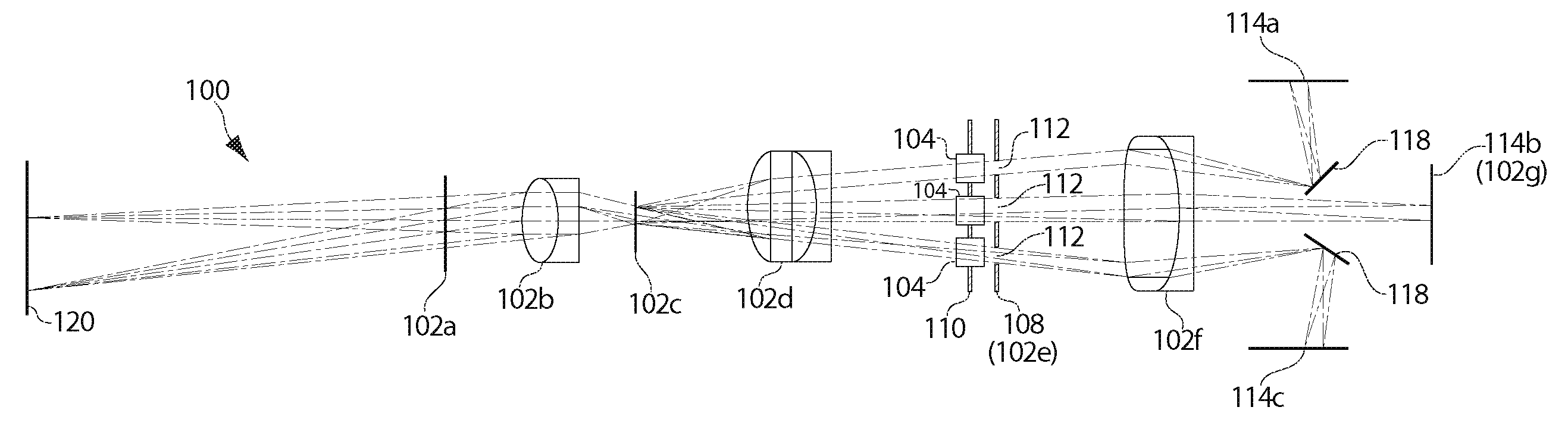
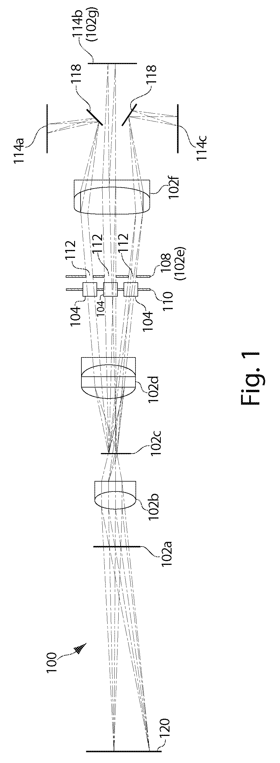
[0038] It will be understood that the ray traces and lenses depicted in the following figures are for purposes of illustration only, and depict optical paths generally in the disclosed systems. The ray traces and lens shapes should not be understood to limit the scope of the invention in any sense including the magnitude, direction, or focus of light rays or bundles passing through various optical components, notwithstanding any variations in number, direction, shape, position or size thereof, except as expressly indicated in the following detailed description.

[0039] Referring to FIG. 1, a schematic diagram of an imaging system 100 in accordance with one preferred embodiment of the present disclosure is depicted, including various optional components. The imaging system 100 may include a primary optical facility 102, which may be employed in any kind of image processing system. In general, a primary optical facility refers herein to an optical system having one optical channel. Typ...


PUM


Abstract

A three-dimensional imaging system uses a single primary optical lens along with various configurations of apertures, refocusing facilities, and the like to obtain three offset optical channels each of which can be separately captured with an optical sensor.

Description

RELATED APPLICATIONS [0001] This application claims the benefit of U.S. Application No. 60 / 773,132 filed on Feb. 13, 2006. [0002] This application is also related to Attorney Docket No. BRNT-0010-P02 entitled “THREE-CHANNEL CAMERA SYSTEMS WITH COLLINEAR APERTURES” and BRNT-0010-P03 entitled “THREE-CHANNEL CAMERA SYSTEMS WITH NON-COLLINEAR APERTURES”, each filed on even date herewith. [0003] Each of the above applications is incorporated herein by reference in its entirety.BACKGROUND [0004] 1. Field of the Invention [0005] This invention relates to the field of imaging, and more particularly to the field of pupil sampling for multi-view three-dimensional imaging. [0006] 2. Description of the Related Art [0007] One approach to capturing three-dimensional depth information is the use of a pair of two-dimensional recording devices whose relative orientation is known. Much like human or animal optical systems, obtaining depth information from stereo optical systems is a triangulation tec...

Claims


Application Information

Patent Timeline
IPC IPC(8): G03B41/08
CPCG03B41/00G03B35/00
Inventor ROHALY, JANOSHART, DOUGLAS P.BRUKILACCHIO, THOMAS J.
Owner MEDIT CORP
Why Eureka
Try Eureka