
Frequency tailored thickness blade for a turbomachine wheel

a turbine wheel and thickness technology, applied in the direction of machines/engines, mechanical equipment, transportation and packaging, etc., can solve the problems of unintentionally intensifying the response of hitherto secondary, reducing the life of the turbine wheel, and creating new resonant responses altogether. , to achieve the effect of reducing the effect of vibratory stress

Inactive Publication Date: 2008-01-17
HONEYWELL INT INC
View PDF19 Cites 5 Cited by
  • Summary
  • Abstract
  • Description
  • Claims
  • Application Information

AI Technical Summary

Benefits of technology

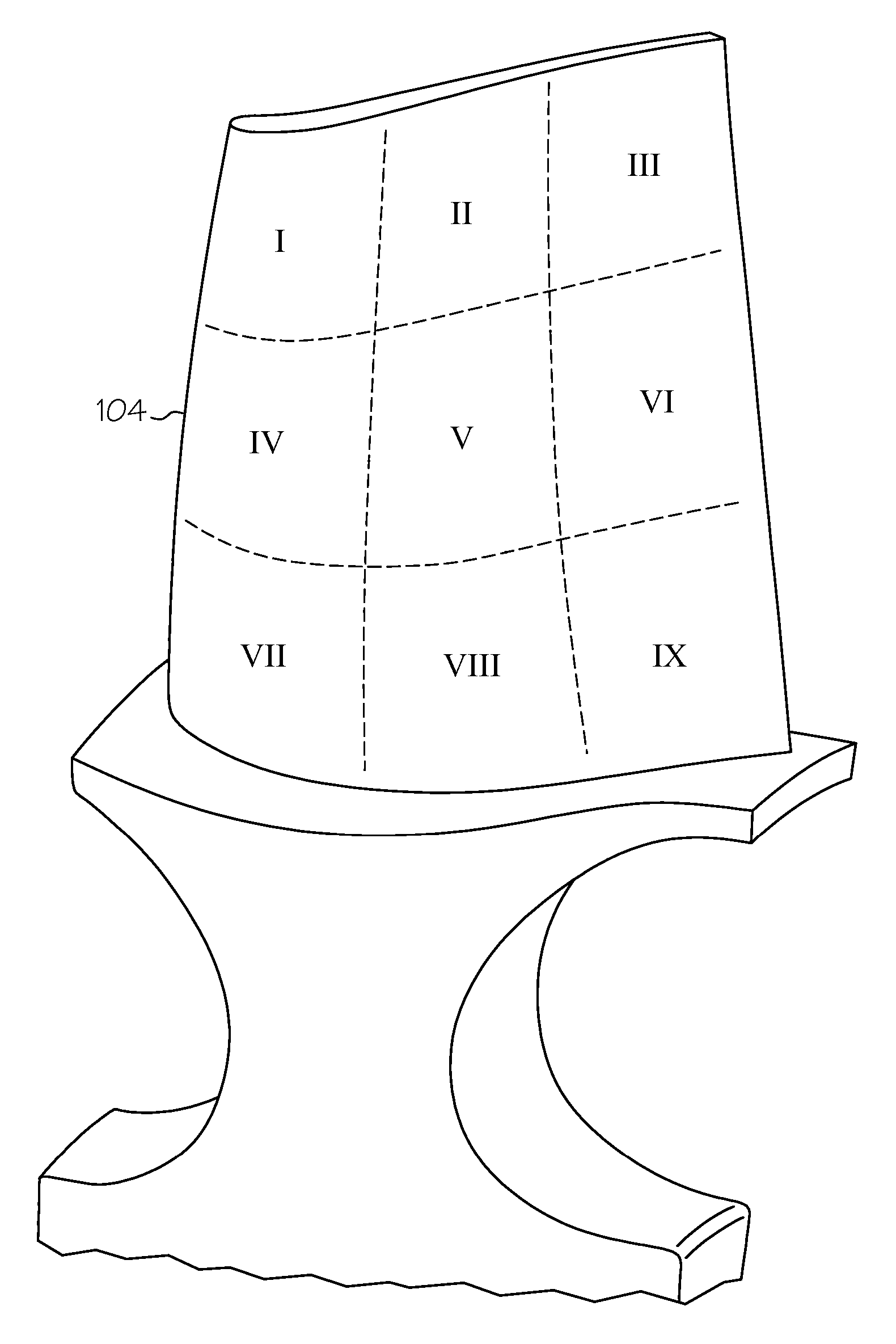
[0009] In one embodiment, and by way of example only, a method is provided for determining a blade topology that reduces the effects of vibratory stress on a turbomachine blade having a plurality of discrete locations, wherein each discrete location has a thickness. The method includes the steps of creating a computational model of the blade, using the computational model to modify the thickness of at least one of the discrete locations a predetermined amount, determining a combination of a discrete location and predetermined thickness amount that reduces vibratory stress on the blade, and applying the determined combination to the computational model to create a revised blade.

Problems solved by technology

Consequently, when the excitation and natural frequencies coincide, the turbine blades, rotor, or sections of the turbomachine may begin to vibrate, potentially causing damage to and / or shortening of the life of the turbine wheel.
Although the above-mentioned modifications may effectively address problematic frequencies, they may unintentionally intensify the response of hitherto secondary (lower responding) modes or may create new resonant responses altogether.
Consequently, these subsequently tuned turbine blades may exhibit other undesirable operational behaviors, including but not limited to, other potential unacceptable vibrational responses, reduced aerodynamic performance, and / or deterioration.

Method used


Image

  • Frequency tailored thickness blade for a turbomachine wheel
  • Frequency tailored thickness blade for a turbomachine wheel
  • Frequency tailored thickness blade for a turbomachine wheel

Examples


Embodiment Construction

[0016] The following detailed description is merely exemplary in nature and is not intended to limit the invention or its application and uses. Furthermore, there is no intention to be bound by any theory presented in the preceding background or the following detailed description. In this regard, before proceeding with the detailed description, it will be appreciated that the present invention is not limited to use with a particular type or configuration of turbine wheel, and it will be appreciated that the embodiments could also be used in conjunction with any wheel having blades extending therefrom and other objects that may be subject to vibration where alternating stress and strains can be accurately measured or predicted during the design of the object.

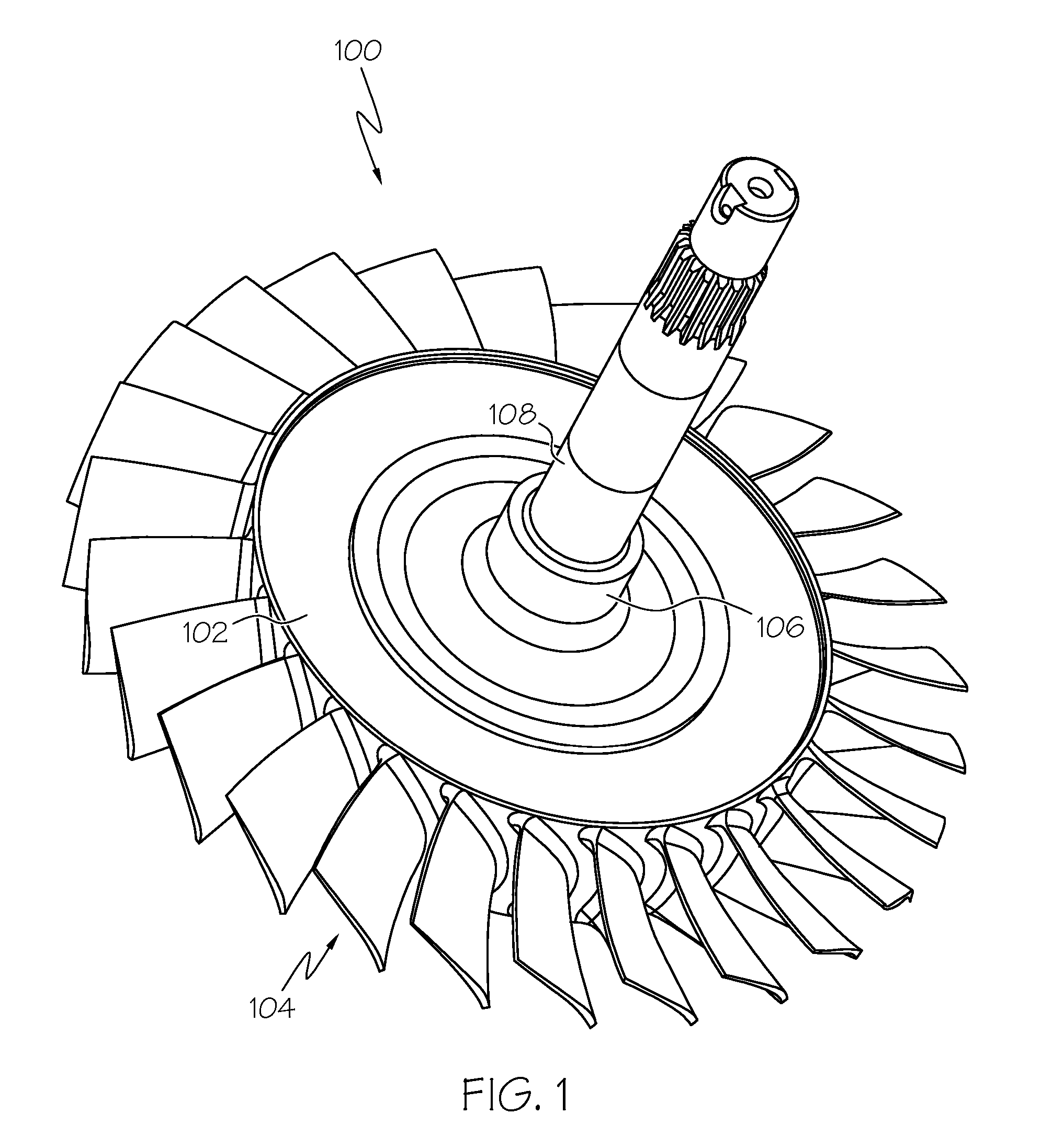
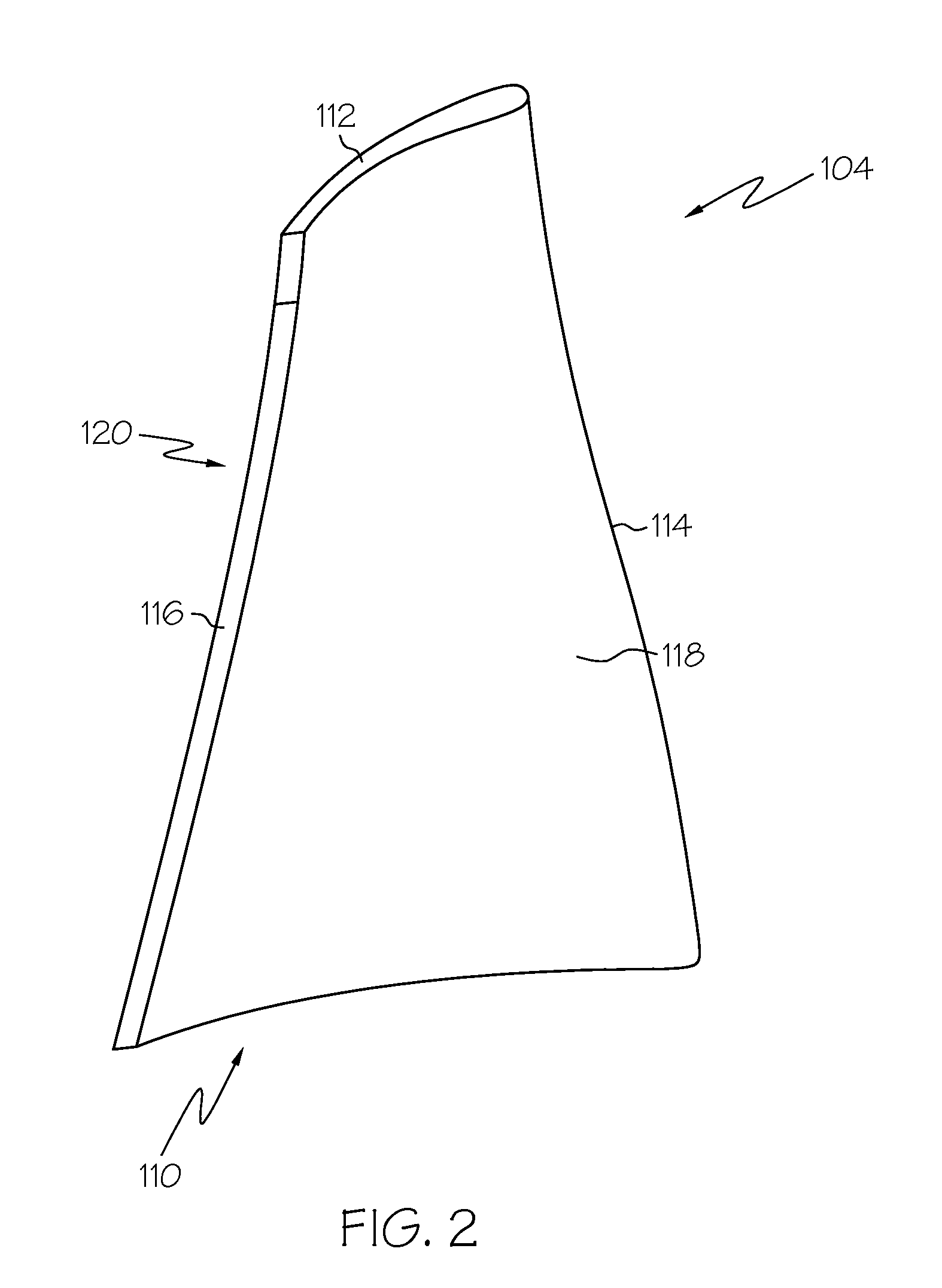
[0017] The blades 104 are arranged around the outer periphery of the hub 102, preferably, in a configuration that optimizes the efficiency of the rotating turbine wheel 100. For example, the blades 104 may be equally spaced apar...


PUM


Abstract

A method is provided for determining a blade topology that reduces the effects of vibratory stress on a turbomachine blade having a plurality of discrete locations, wherein each discrete location has a thickness. The method includes the steps of creating a computational model of the blade, using the computational model to modify the thickness of at least one of the discrete locations a predetermined amount, determining a combination of a discrete location and predetermined thickness amount that reduces vibratory stress on the blade, and applying the determined combination to the computational model to create a revised blade. A turbomachine including a blade having the determined blade topology is also provided.

Description

CROSS REFERENCE TO RELATED APPLICATION [0001] This application is a divisional of Ser. No. 10 / 959,450 filed on Oct. 5, 2004.TECHNICAL FIELD [0002] The present invention relates to turbomachines and, more particularly, to a blade of a turbine wheel. BACKGROUND [0003] Turbomachines are used in myriad applications, including in air turbine starters used in aircraft engines. Typically, a turbomachine includes a turbine wheel comprised of a plurality of turbine blades that are each mounted to a rotor. Generally, each blade is similarly sized and shaped. The turbine blades are spaced apart and positioned such that the rotor rotates when a pressure differential is created across the two sides of the turbine wheel. [0004] During a start cycle, the turbine blades may experience periodic mechanical and / or aerodynamic excitation from various sources, such as from flow irregularities emanating from upstream or downstream blade rows, gear mesh clatter, and imperfections that may be present in on...

Claims


Application Information

Patent Timeline
Patent Type & Authority Applications(United States)
IPC IPC(8): B64C27/46
CPCF01D5/141Y02T50/673F01D5/16Y02T50/60
Inventor GENTILE, DAVID P.KINCHELOE, TODD A.
Owner HONEYWELL INT INC
Learn More