Coupling Device for Media Conduits

Inactive Publication Date: 2008-01-17
VOSS AUTOMOTIVE
9 Cites 1 Cited by

AI-Extracted Technical Summary

Problems solved by technology

In addition, the installation is also sometimes difficult because the fixing of the one coupling plate merely by latching (pre-fixing) during the coupling operation is often not sufficiently secure, and therefore the coup...

Method used

[0034] In another embodiment illustrated in FIG. 17, the receiving openings S, M are located close to the axis of symmetry X, and therefore the passage holes 22 and the extension pieces 26 can be arranged with the screw holes 24 in the outer edge region of the coupling parts. This advantageously results in better accessibility to the screws 28 during installation, particularly when conduits are fitted which are already connected via the connecting pieces 14, 16 to the plug-in coupling parts 4, 6 sitting in the receiving openings S, M.
[0043] The coupling device may be configured to make insertion of the plug-in coupling parts easier than their removal. As shown in FIG. 16 in conjunction with FIGS. 8 and 9, in one embodiment the annular groove 66 of each plug-in coupling part 4, 6 and each latching extension piece 64 of the latching arms 56, 58 of the coupling ...

Benefits of technology

[0007] In another embodiment of the invention, each coupling part also has substantially identical means, firstly, for securing it to an installation wall and, secondly, for the mutual connection to the respectively other coupling part. The two holding connections advantageously take place with the use of self-tapping or self-thread-forming screws which are each screwed d...

Abstract

A coupling device for tubes and/or pipes is claimed comprising two substantially identical plate-type coupling parts. Each coupling part has an even number of openings to receive inserted plug-in couplings configured as plug parts or socket parts. In one embodiment, the receiving openings for plug parts are arranged mirror-symmetrically across an axis of symmetry from the receiving openings for socket parts. The plug and socket parts are joined by first inserting and securing them into their respective receiving openings in the two coupling parts, then connecting the coupling parts. The coupling device may be attached to an opening in an installation wall, for example, the bulkhead of a motor vehicle.

Application Domain

Technology Topic

EngineeringAxis of symmetry +2

Image

  • Coupling Device for Media Conduits
  • Coupling Device for Media Conduits
  • Coupling Device for Media Conduits

Examples

  • Experimental program(1)

Example

[0023] In order that the present invention may be more readily understood, embodiments thereof will now be described, with reference to the accompanying drawings. The following description is merely exemplary in nature and is in no way intended to limit the invention or its application or uses.
[0024] In the various figures of the drawing, identical parts are provided with the same reference numbers. Each description of a part, which is possibly only undertaken once with reference to one of the figures of the drawing, applies analogously with respect to the other figures of the drawing in which that part can likewise be seen with the corresponding reference number.
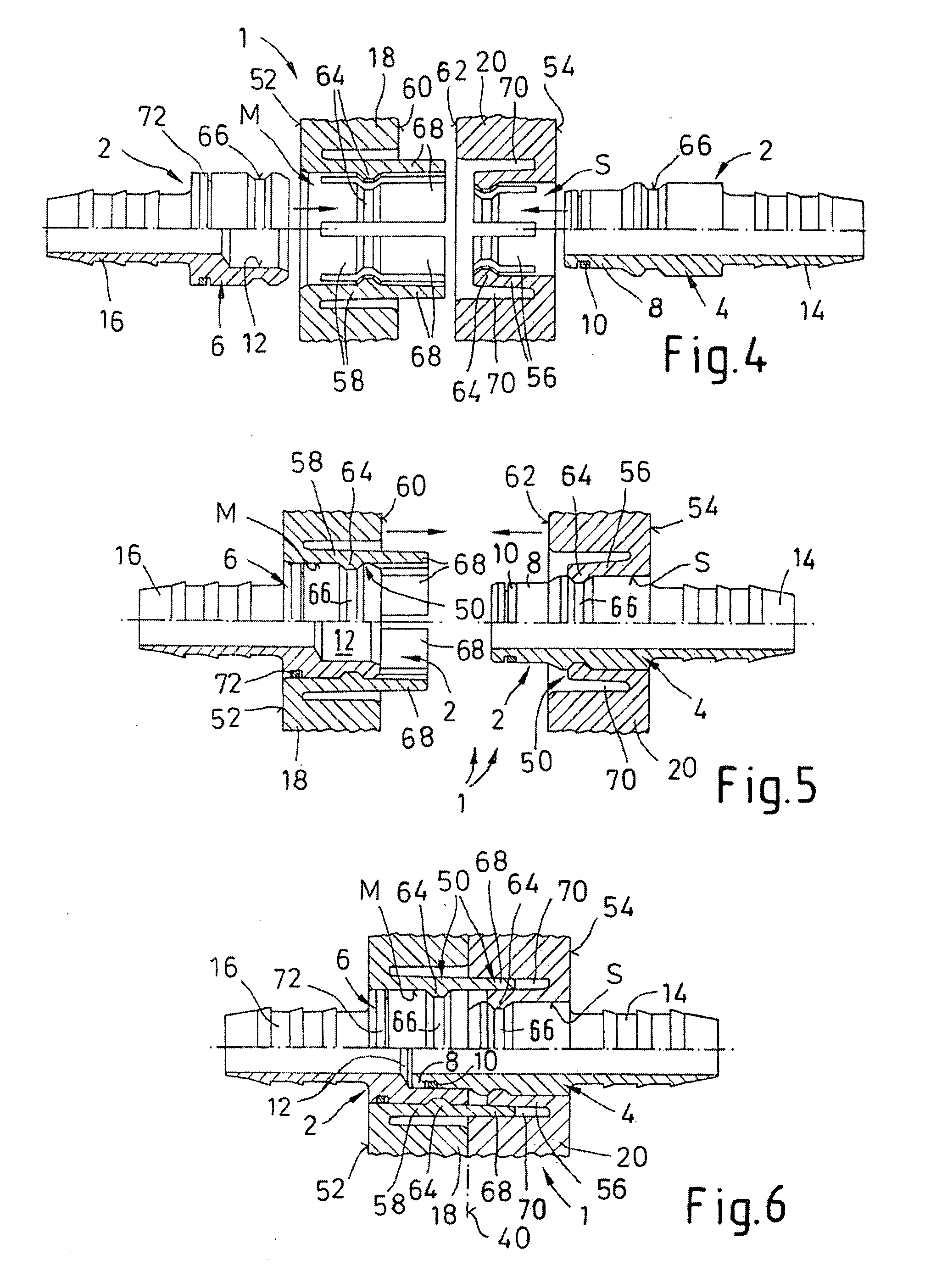
[0025] A coupling device 1 according to the invention is provided for an even number of at least two, and in the illustrated embodiment six, plug-in couplings 2. The coupling device comprises two plug-in coupling parts, a plug part 4 and a socket part 6. As best seen in FIGS. 4-6, each plug part 4 has a plug stem 8 which can be inserted in a circumferentially sealed manner, in particular via a sealing ring 10 sitting in an outer annular groove, into a plug-in receptacle 12 of the corresponding socket part 6 (see FIG. 6 in this respect).
[0026] At its end facing away from the plug stem 8, each plug part 4 has a connecting piece 14, designed in particular as a customary drive-in spike. Similarly, each socket part 6 has a connecting piece 16 which faces axially away from the plug-in receptacle 12 and is likewise preferably designed as a drive-in spike. These connecting pieces 14, 16 serve to connect media conduits (not illustrated), in particular plastic pipes (preferably made of PA), by each conduit being placed onto one of the connecting pieces 14, 16.
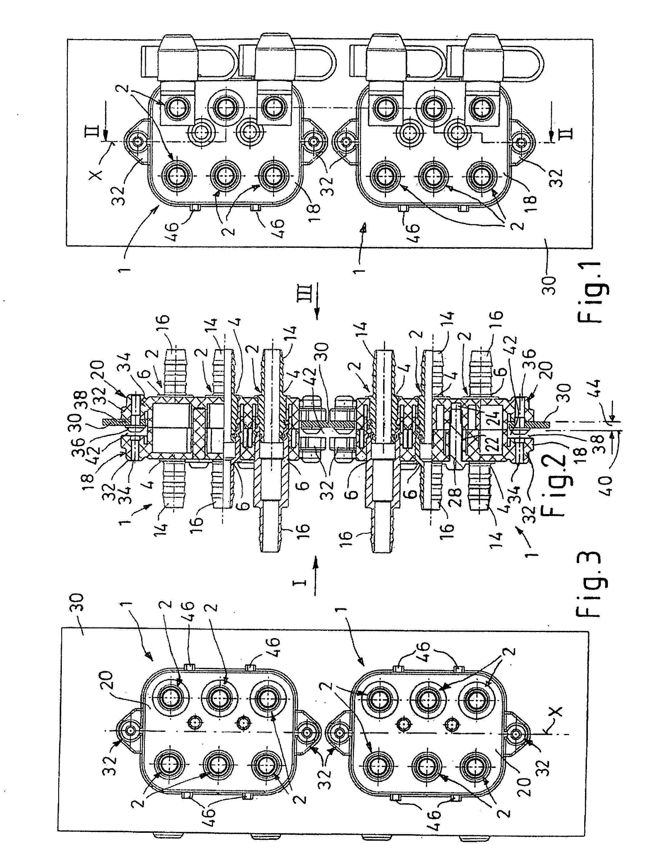
[0027] As shown in FIGS. 1-31 the coupling device 1 furthermore has two essentially plate-like coupling parts 18, 20 for the securing and retention of the plug-in coupling parts 4, 6 of the plug-in couplings 2. Returning to the enlarged sectional views of FIGS. 4-6, in the region of each plug-in coupling 2, the one coupling part (e.g. 18) has a receiving opening S for the plug part 4 while the other coupling part (e.g. 20) has a receiving opening M for the associated socket part 6 (see FIGS. 4-15). The coupling parts 18, 20 can be connected to each other in an essentially parallel arrangement in such a manner that the receiving openings S, M are located opposite each other in an axially aligned manner, and the plug-in coupling parts 2, 4 sitting in each case in the receiving openings S, M are plugged together when the coupling parts 18, 20 are joined together. This can be easily understood with reference to FIGS. 5 and 6.
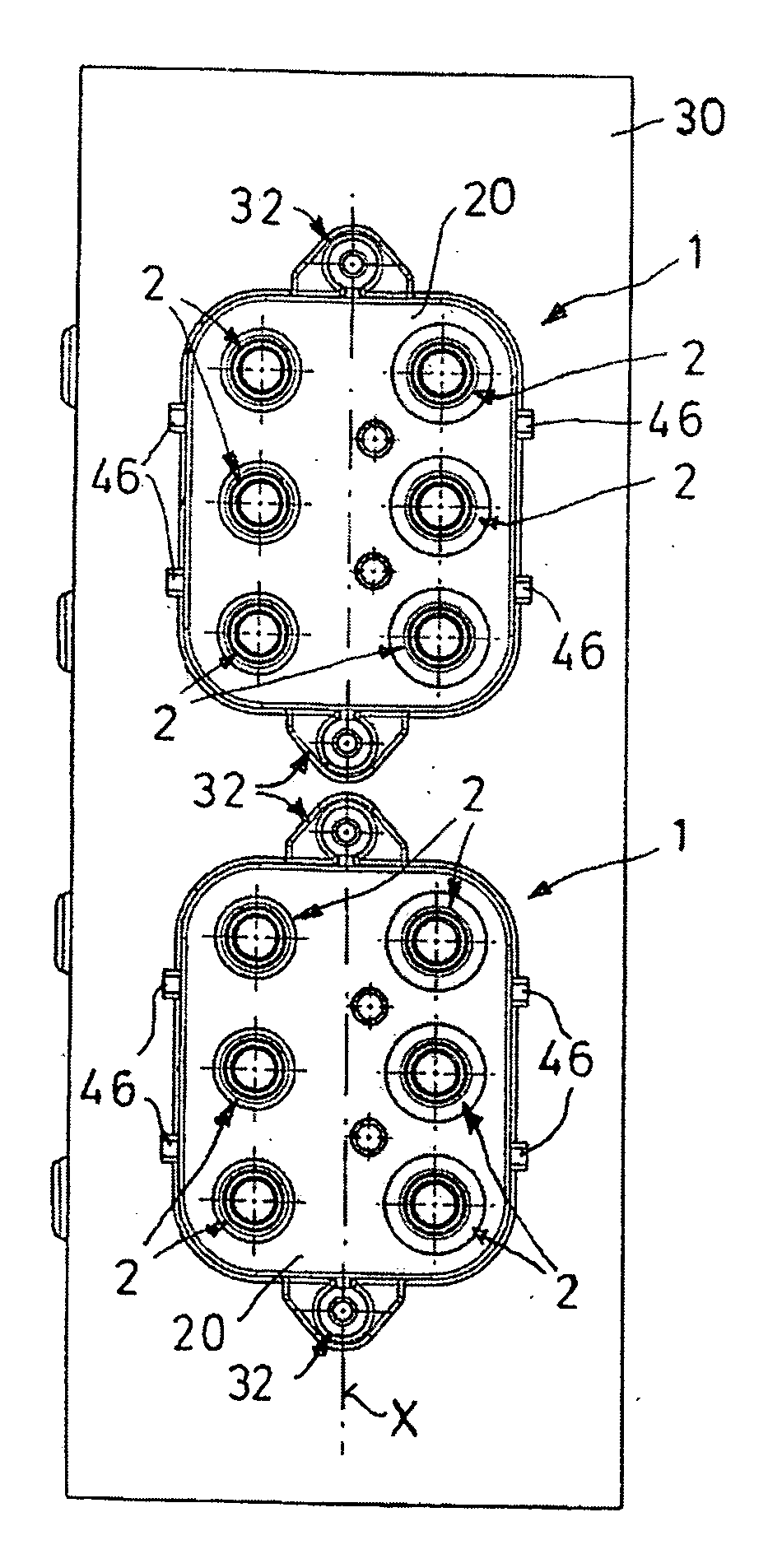
[0028] The socket part receiving openings M understandably have a greater opening cross section than the plug part receiving openings S. In addition, the receiving openings S, M differ slightly with regard to the securing of the plug and socket parts 4, 6. This is explained in more detail further below.
[0029] According to the invention, it is provided that the two coupling parts 18 and 20 are designed at least substantially identically, in one embodiment as single-piece, monolithic plastic molded parts in each case. Production in one and the same forming die is advantageously possible because of the substantial identicality. The coupling parts 18, 20 are expediently composed of a fiber-reinforced plastics material, for example PA66-GF30.
[0030] Each of the substantially identical coupling parts 18, 20 has both a certain number of receiving openings S—for example three, as illustrated—for plug parts 4 and the same number of receiving openings M for socket parts 6. In each coupling part 18 or 20, the two types of receiving openings S and M are each arranged symmetrically opposite each other in pairs with respect to an axis of symmetry X. By this means, the coupling parts 18 and 20 can be connected from an identical initial position in space by rotation of one of the coupling parts through 180° about the axis of symmetry X relative to the other coupling part for the purpose of coupling the plug-in couplings 2 or the plug and socket parts 4, 6. It should be noted that, for the coupling device 1 to be capable of functioning, not all of the receiving openings S, M present have to be equipped with plug parts 4 or socket parts 6; it suffices if one of the coupling parts has (at least) one plug part 4 and the other coupling part has a socket part 6 (at least) in the associated receiving opening M.
[0031] An advantage of a symmetrical arrangement of the receiving openings S and M is that the coupling parts 18, 20 can be coupled to each other only in a relative position. Consequently, the mutually assigned plug and socket parts 4, 6 cannot be mixed up during the connection.
[0032] There are various possibilities for the arrangement and distribution of the two types of receiving openings S and M on the surface of the respective coupling part 18, 20. According to FIGS. 7-13, receiving openings S or M of the same type can be arranged in each case on each side of the axis of symmetry X. As illustrated by way of example in FIGS. 14 and 15, different types of receiving openings S and M may also be arranged on each side next to the axis of symmetry X, but the respectively other type of receiving opening has to be provided mirror-symmetrically opposite in each case.
[0033] Each coupling part 18 or 20 has, for the mutual connection to the respectively other coupling part 20 or 18, at least one passage hole 22 and at least one screw hole 24 in a mutually opposite arrangement symmetrically with respect to the axis of symmetry X. Preferably, in each case two passage holes 22 and two screw holes 24 are provided which are spaced apart from one another in the direction of the axis of symmetry X or parallel thereto. Each screw hole 24 is designed in particular as a blind hole extending as a tube- or bulge-like extension piece 26 from the outer, or rear, side of the coupling part in such a manner that a self-tapping, i.e. self-thread-forming, screw 28 (see FIG. 2) can be screwed in each case through the passage hole 22 of the one coupling part 18/20 directly into the screw hole 24 of the other coupling part 20118. The passage holes 22 and screw holes 24 can be located in each case in a surface region between the receiving openings S, M. In this case, said holes 22, 24 may lie close to the axis of symmetry X in order to connect the two coupling parts 18, 20 to each other in a sufficiently fixed manner over their entire surface region.
[0034] In another embodiment illustrated in FIG. 17, the receiving openings S, M are located close to the axis of symmetry X, and therefore the passage holes 22 and the extension pieces 26 can be arranged with the screw holes 24 in the outer edge region of the coupling parts. This advantageously results in better accessibility to the screws 28 during installation, particularly when conduits are fitted which are already connected via the connecting pieces 14, 16 to the plug-in coupling parts 4, 6 sitting in the receiving openings S, M.
[0035] For the fastening in the region of a correspondingly sized conduit passage opening in an installation wall 30 (“bulkhead wall”, see FIGS. 1-3), each coupling part 18, 20 has at least two fastening sections 32 with installation holes 34 preferably lying on the axis of symmetry X. In one embodiment, said installation holes 34 are designed for the direct screwing-in of self-tapping screws 36. As seen in FIG. 2, only one of the two coupling parts 18, 20 is fastened to the installation wall 30 by the screws 36 being screwed through passage holes in the installation wall 30 into the installation holes 34 of the coupling part to be fastened in each case (e.g. 20). By this means, the coupling part 20 is fixed very securely to the installation wall 30. The other coupling part (e.g. 18) can subsequently be fitted and fastened with the screws 28 to the coupling part 20 which is fastened to the installation wall 30. In this situation, and as shown in FIG. 2, the fastening sections 32 and installation holes 34 of the other coupling part 18 are not used; instead coupling part 18 is fastened to the other coupling part 20. Each fastening section 32 has a wall bearing surface 38 which, as seen in FIG. 2, is offset parallel in relation to a coupling plane 40, which is located centrally between the connected coupling parts 18, 20. This offset wall bearing surface configuration allows sufficient clearance between the respectively mutually opposite fastening sections 32 of the two connected coupling parts 18, 20, allowing the device to receive a holding section of the installation wall 30 and, if appropriate, a screw head of the screw 36. Said offset between the bearing surface 38 and the coupling plane 40 is shown in FIG. 2 by the reference number 44. The clearance 42 between the two connected coupling parts is twice the distance of offset 44.
[0036] In the exemplary embodiments illustrated, each coupling part 18, 20 has a substantially rectangular surface form with preferably rounded corners. In the embodiments according to FIGS. 1-3 and 7-10, it is provided that the fastening sections 32 are formed on opposite sides of the rectangle, in particular the narrow sides, as extension pieces which protrude beyond the rectangular surface form. The advantage of this embodiment is that the installation wall 30 can have a simple, correspondingly rectangular passage opening. In one alternative embodiment according to FIGS. 11-15, the fastening sections 32 are formed as subregions within the surface form of the respective coupling part 18, 20. The advantage of this embodiment is a reduced space requirement in the case of a multiple arrangement of coupling devices (cf. FIGS. 1-3) in that the coupling devices 1 can be arranged closer together on the installation wall 30. However, in this embodiment, the installation wall 30 would ordinarily have inwardly extending wall sections in the region of the installation holes 34.
[0037] In both embodiments, the arrangement of the installation holes 34 on the axis of symmetry X permits any desired installation sequence, i.e. it is insignificant whether the coupling part 18 or the coupling part 20 is fastened on the particular side of the installation wall 30.
[0038] Since all of the above mentioned screw connections are arranged on or in the vicinity of the axis of symmetry X, it is advantageous if each coupling part 18 or 20 has at least two edge bearing elements 46 which are located opposite each other with respect to the axis of symmetry X and are intended for bearing against the installation wall 30 in a manner preventing tilting. As illustrated, a total of four bearing elements 46 can be provided in a paired arrangement on both longitudinal sides of each coupling part 18, 20.
[0039] Each plug-in coupling part 4, 6 may be fixed in the associated receiving opening S, M of the respective coupling part 18, 20 via latching means 50. As shown in FIGS. 5 and 6, the latching means provide that a plug-in coupling part 4 or 6, can be releasably latched with the coupling parts 18, 20 prior to coupling parts 18 and 20 being connected. (See FIGS. 4 and 5 in this respect). More particularly, plug part 4 can be inserted and fixed in opening S by a releasable latch from the rear side 52, 54 of coupling part 18 or 20. Similarly, socket part 6 can be releasably latched and fixed from the rear side of the other coupling part. In the connected state of the coupling parts 18, 20—see FIG. 6—the plug-in coupling parts (i.e. plug part 4 and socket part 6) are held in a form-fitting and therefore unreleasable manner by, in particular, automatic or mutual locking of the latching means 50.
[0040] In the exemplary embodiment illustrated in FIGS. 4-6, each coupling part 18, 20 has, as latching means 50, radially biased spring-elastic latching arms 56 and 58 which are distributed in each case over the circumference of the receiving opening S and M (and thus virtually form the respective receiving opening) and, in each case starting from the rear side 52 or 54 of the coupling part 18 or 20, extend essentially in or parallel to the joining direction of the plug-in couplings 2. In this case, in their region which faces the coupling side 60 or 62 of the respective coupling part 18, 20, the latching arms are movable in a spring-elastic manner in the radial direction. The latching arms 56, 58 have latching extension pieces 64 which protrude radially inward into the receiving opening S or M. Each extension piece 64 interacts in a latching manner with a circumferential annular groove 66 of the respective plug-in coupling part 4 or 6. In this embodiment, it is further provided that, in the region of each socket part receiving opening M, the latching arms 58 have locking extension pieces 68 which point in the joining direction. When the coupling parts 18, 20 are connected to each other, the extension pieces 68 engage in the axial direction with an annular gap 70, which surrounds the latching arms 56 of the other coupling part, in such a manner that all of the latching arms 56, 58 of the two coupling parts 18, 20 are then supported (locked) against a radial movement. This can readily be seen in FIG. 6. The locking extension pieces 68 connected to the latching arms 58 are supported on an outer annular surface which delimits the annular gap 70 to the outside, and the latching arms 56, for their part, are supported on the inner surfaces of the locking extension pieces 68. In this manner, the latching arms 56, 58 cannot move radially outward in this position, and therefore the coupling parts 4, 6 are held in a form-fitting and virtually nonreleasable manner. However, release is possible by separating the two coupling parts 18, 20. From the pre-connected state illustrated in FIG. 5, the plug-in coupling parts 4, 6 can be pulled out of the receiving openings S, M by overcoming the strong form fit of the latching means 50.
[0041] In particular in the case of vehicle applications, it is also advantageous if the plug-in coupling parts 4, 6 are circumferentially sealed in the respective receiving opening S, M. As illustrated in FIGS. 4-6 using the example of the socket part 6, for this sealing the respective plug-in coupling part 416 can have a sealing ring 72 in an outer annular groove, the sealing ring being arranged in a circumferentially closed, continuous “joining region” of the latching arms 58 (or 56), i.e. in that region of the respective receiving opening S or M which directly adjoins the outer, rear mouth. Although not shown in FIGS. 4-6, a seal of this type may also be provided in the region of the plug part 4.
[0042] As shown in FIG. 16, the plug-in coupling parts 4, 6 may each have a stop element 74 as an insertion limitation in order to prevent the plug part 4 or the socket part 6 from being inserted too far into or through the respective coupling part 18, 20. In the example illustrated, an annular collar is provided in each case as the stop element 74 in such a manner that, in the correctly latched use position, the stop element 74 comes to bear in the region of the rear side 52, 54 of the respective coupling part 18, 20.
[0043] The coupling device may be configured to make insertion of the plug-in coupling parts easier than their removal. As shown in FIG. 16 in conjunction with FIGS. 8 and 9, in one embodiment the annular groove 66 of each plug-in coupling part 4, 6 and each latching extension piece 64 of the latching arms 56, 58 of the coupling parts 18, 20 firstly have, on their sides interacting in the insertion direction of the plug-in coupling parts 4, 6, first oblique surfaces 76, and secondly have, on their sides interacting in the removal direction, second oblique surfaces 78. In this case, the first oblique surfaces 76 enclose a first angle α1 and the second oblique surfaces 78 enclose a second angle α2 in each case measured relative to the plug-in axis 80. In this case, the first angle α1 is preferably smaller than the second angle α2. The effect achieved by this is that the plug-in coupling parts 4, 6 can be inserted with a lower force than they can be pulled out of the respective receiving opening S, M. The first angle α1 preferably lies in the range of from 15° to 60°, in particular 30° to 45°, while the second angle α2 is to lie in the range of from 30° to 90°, in particular 45° to 60°.
[0044] In this connection, the stop elements 74 of the plug and socket parts 4, 6 are particularly advantageous because they inhibit insertion beyond the actual latching position which would cause the latching arms 56, 58 to be expanded again and, as a result, the coupling parts 18, 20 could only be coupled with difficulty or could even no longer be coupled. Without the stop elements 74, this risk would be particularly great because of the smaller angle α1. As the angle of α2 is increased, (up to 90° for a form fit=nonreleasable), the likelihood decreases that the physical coupling of coupling parts 18, 20 would result in the plug-in coupling parts 4, 6 being pulled or pushed out of the respective coupling part 18, 20 by preassembled conduits.
[0045] The features disclosed in the foregoing description, or the following claims, or the accompanying drawings, expressed in their specific forms or in terms of a means for performing the disclosed function, may, separately, or in any combination of such features, be utilized for realizing the invention in diverse forms thereof. While the above description constitutes one or more embodiments of the present invention, it will be appreciated that the invention is susceptible to modification, variation and change without departing from the proper scope and fair meaning of the accompanying claims.

PUM

no PUM

Description & Claims & Application Information

We can also present the details of the Description, Claims and Application information to help users get a comprehensive understanding of the technical details of the patent, such as background art, summary of invention, brief description of drawings, description of embodiments, and other original content. On the other hand, users can also determine the specific scope of protection of the technology through the list of claims; as well as understand the changes in the life cycle of the technology with the presentation of the patent timeline. Login to view more.

Similar technology patents

Classification and recommendation of technical efficacy words

Why Eureka
Try Eureka