Yoke for universal joint

a universal joint and yoke technology, applied in the direction of fastening means, yielding couplings, pipes, etc., can solve the problem of incomplete transmission of torque, achieve reliable coupling and fixed, and prevent noise from occurring, the effect of preventing transmission of torqu

Active Publication Date: 2008-01-17
KOYO MASCH IND CO LTD
View PDF5 Cites 1 Cited by
  • Summary
  • Abstract
  • Description
  • Claims
  • Application Information

AI Technical Summary

Benefits of technology

[0010] According to the invention, a yoke for universal joint, to which one end of a rotating shaft having two planes parallel to each other is connected, includes a base portion and a pair of opposed side walls that extend from the base portion so as to face each other at a distance. The one end of the rotating shaft is inserted between the opposed side walls such that both planes of the rotating shaft at the one end are opposed to the opposed side walls and the outer periphery of the rotating shaft at the one end is abutted on the base portion. The inserted rotating shaft is interposed and fixed by the base portion and the opposed side walls when fastening portions of the opposed side walls at the leading ends thereof are fastened by a fastener. A concave portion is formed in a portion, which is abutted on an outer peripheral square portion of the rotating shaft at the one end, between the fastening portion and the base portion in one or both inner surfaces of the opposed side walls. An opening peripheral edge square portion of the concave portion is pushed against the outer peripheral square portion of the rotating shaft in both sides of the fastening portions in the axial direction of the rotating shaft by the fastening of the fastener.
[0011] In accordance with the invention, one end of the rotating shaft is inserted between the opposed side walls such that two planes thereof are opposed to the inner surfaces of the respective opposed side walls and the outer periphery thereof is abutted on the inner surface of the base portion, and the fastening portion of the opposed side walls at the leading end is fastened by the fastener. Then, the one end of the rotating shaft is interposed by the base portion and the opposed side walls, and the yoke and the rotating shaft are coupled and fixed to each other.
[0012] At this time, the leading ends of the opposed side walls are deformed by the fastening of the fastener such that the opposed side walls approach each other. By the deformation of the opposed side walls, the opening peripheral square portion of the concave portion is pushed against the outer peripheral square portion of the rotating shaft, and one of the opening peripheral edge square portion and the outer peripheral square portion bites the other in both sides of the fastening portion in the axial direction of the rotating shaft.
[0013] Accordingly, the rotating shaft can be pressed at two positions with the fastening portion interposed therebetween. Further, when the yoke and the rotating shaft are relatively rotated around the axis parallel to the opposed direction of the opposed side walls or are relatively moved in the axial direction of the rotating shaft due to an external force or vibration acting on the yoke and the rotating shaft, the positional relationship between the yoke and the rotating shaft is prevented from being deviated.
[0014] According to the yoke for universal joint of the invention, the rotating shaft is not only interposed by the base portion and the opposed side walls through the fastening of the fastener, but also one of the opening peripheral edge square portion of the concave portion and the outer peripheral square portion of the rotating shaft bites the other in both sides of the fastening portion. Therefore, the yoke and the rotating shaft can be more reliably coupled and fixed to each other. Accordingly, without a deviation occurring between the yoke and the rotating shaft, noise can be prevented from occurring, and the transmission of torque can be prevented from being incomplete.
[0015] Preferably, the concave portion is both of the opposed side walls, not in one of them. Then, it is possible to implement a coupling structure with no rattling.

Problems solved by technology

Such a deviation results in noise and makes the transmission of torque incomplete.

Method used


Image

  • Yoke for universal joint
  • Yoke for universal joint
  • Yoke for universal joint

Examples


Embodiment Construction

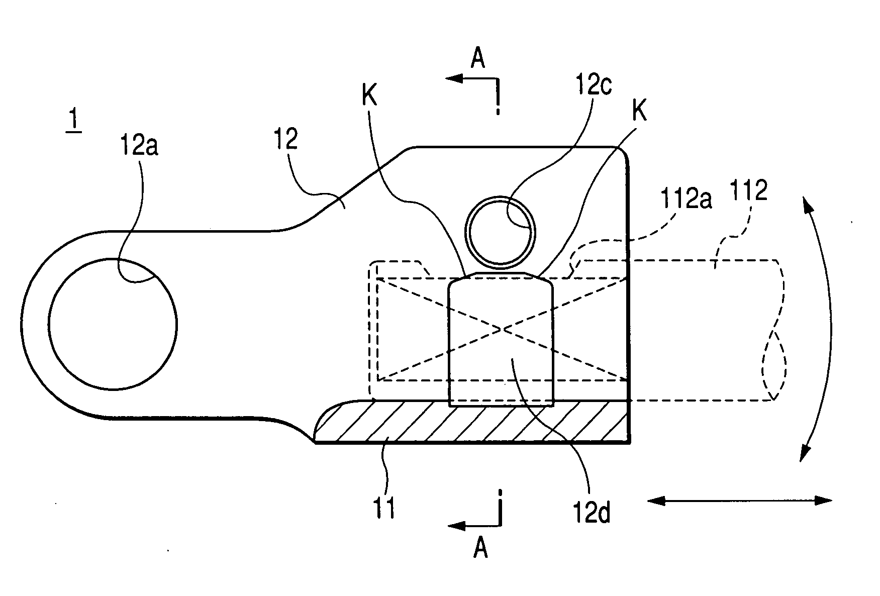
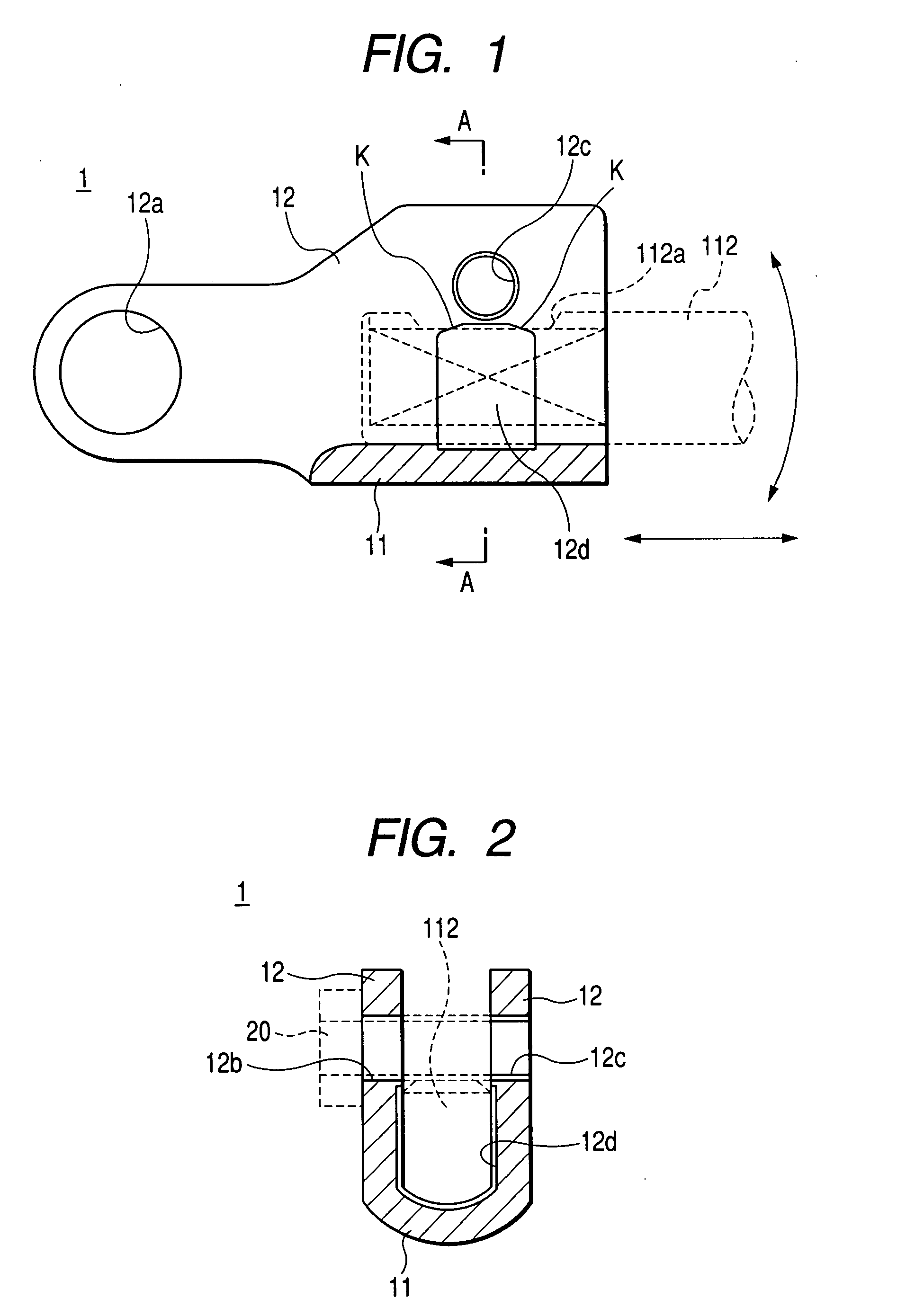
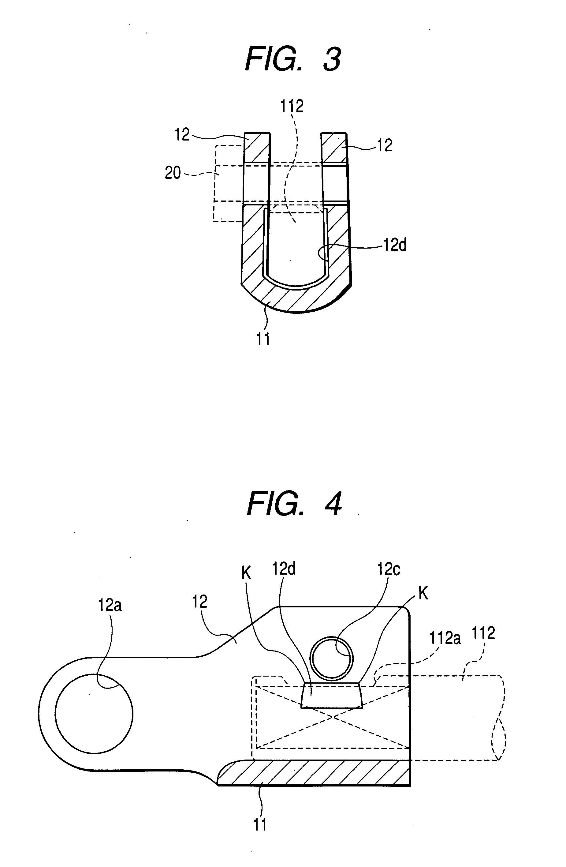
[0028] Hereinafter, a preferred embodiment of the present invention will be described with reference to accompanying drawings. FIG. 1 is a cross-sectional view illustrating a schematic construction of a yoke for universal joint according to an embodiment of the invention, and FIG. 2 is a cross-sectional view taken along line A-A of FIG. 1. In the following descriptions, the yoke 1 for universal joint of this embodiment shown in FIGS. 1 and 2 will be provided in place of the second yoke 103 shown in FIGS. 8 to 10. In the descriptions excluding the yoke 1, the same reference numerals will be attached, and the detailed descriptions thereof will be omitted.

[0029] The yoke 1 for universal joint (the second yoke) of this embodiment is formed of a material having lower hardness than the input shaft 112 of the steering gear. As shown in FIGS. 1 and 2, the yoke 1 for universal joint includes a base portion 11 and a pair of opposed side walls 12 which extend upward from the base portion 11 s...


PUM


Abstract

A yoke for universal joint includes a base portion and a pair of opposed side walls and is connected to one end of a rotating shaft having two planes parallel to each other. One end of the rotating shaft is inserted between the opposed side walls such that both planes oppose the respective opposed side walls and the lower surface is abutted on the base portion. Then, a fastening portion of the opposed side walls in the upper portions thereof is fastened by a bolt such that the rotating shaft is interposed and fixed. On the inner surfaces of the opposed side walls, the concave portion is formed under the fastening portion. The concave portion is pushed against the outer peripheral square portion of the rotating shaft in both sides of the fastening portion in the axial direction of the rotating shaft.

Description

BACKGROUND OF THE INVENTION [0001] The present invention relates to a yoke for universal joint including a base portion and a pair of opposed side walls which extend from the base portion so as to face each other at a distance. In the yoke, one end of a rotating shaft inserted between the opposed side walls is interposed and fixed by the base portion and the opposed side walls when fastening portions of the opposed side walls at the leading ends thereof are fastened by a fastener. [0002] A universal joint 100 serves to connect two shafts, of which the shaft lines intersect at a certain angle, so as to transmit the torque of one shaft to the other shaft. As shown in FIG. 8, the universal joint 100 includes a cross joint 101, of which the shaft lines cross each other, and two yokes 102 and 103 (a first yoke 102 and a second yoke 103), which are respectively connected to both ends of the shafts composing the joint cross 101 so as to rock around the shaft lines and to which one ends of ...

Claims


Application Information

Patent Timeline
Patent Type & Authority Applications(United States)
IPC IPC(8): F16D3/00
CPCF16D1/0864Y10T403/4617F16D3/387
Inventor KAKIMOTO, KAZUHIDEKAWAI, HISATSUGUKOBAYASHI, AKIOKOYAMA, TAKESHI
Owner KOYO MASCH IND CO LTD
Why Eureka
Try Eureka