Pattern measurement apparatus and pattern measuring method

a technology of measurement apparatus and pattern, which is applied in the direction of image enhancement, semiconductor/solid-state device testing/measurement, instruments, etc., can solve the problems of difficult to judge whether intervals between edges constitute line patterns or space patterns, and risk of misjudging whether a portion between edges constitutes line patterns

Active Publication Date: 2008-01-17
ADVANTEST CORP
View PDF6 Cites 2 Cited by
  • Summary
  • Abstract
  • Description
  • Claims
  • Application Information

AI Technical Summary

Benefits of technology

[0017] Moreover, another object of the present invention is to provide a pattern measurement apparatus and a pattern measuring method capable of accurately specifying irregularities in a measurement target region without being influenced by luminance of a pattern.
[0020] According to the present invention, the second derivative profile is created by differentiating twice the line profile and a judgment is made as to whether the edge in the pattern is the rising edge or the falling edge by use of the two peak positions and the two peak values, which positions appear in the vicinity of the edge position of the pattern obtained from the second derivative profile. In this judgment, assuming that the two peak positions are defined as X1 and X2, for example, signal intensity in the position X1 is compared with signal intensity in the position X2. Then, the edge position is judged as the rising edge in the direction from the position X1 to the position X2 when the signal intensity in the position X1 is larger than the signal intensity in the position X2. In this way, even in the case of a line-and-space pattern including line patterns and space patterns formed almost at even intervals, it is possible to detect the line pattern reliably.
[0022] In the present invention, the second derivative profile is created by differentiating twice the line profile and a judgment is made as to whether the edge in the pattern is the rising edge or the falling edge by use of the two peak positions and the two peak values which peak positions appear in the vicinity of the edge position of the pattern obtained from the second derivative profile. In this way, even in the case when a line width and a space width are almost equal, it is possible to identify the line pattern and to measure the width of the line pattern.

Problems solved by technology

However, application of these methods of detecting the edge position to the line-and-space pattern turns out to cause the following problem.
When the width of a line pattern is approximately equal to the width of a space pattern, it is possible to detect edges, but it is difficult to judge whether intervals between the edges constitute the line pattern or the space pattern.
In such cases, there is a risk of misjudging whether a portion between the edges constitutes the line pattern or the space pattern.

Method used


Image

  • Pattern measurement apparatus and pattern measuring method
  • Pattern measurement apparatus and pattern measuring method
  • Pattern measurement apparatus and pattern measuring method

Examples


Embodiment Construction

[0032] Now, an embodiment of the present invention will be described below with reference to the accompanying drawings.

[0033] A configuration of a scanning electron microscope used as a pattern measurement apparatus will be described in the first place. Then, a typical method of measuring a line width of a pattern will be described. Thereafter, pattern detection in the case where lines and spaces are formed at almost even intervals will be described. In particular, a pattern detecting method capable of distinguishing between lines and spaces in the case of reversed tones of the lines and the spaces will be described herein. Lastly, a pattern measuring method using the pattern detecting method of the present invention will be described.

(Configuration of a Scanning Electron Microscope)

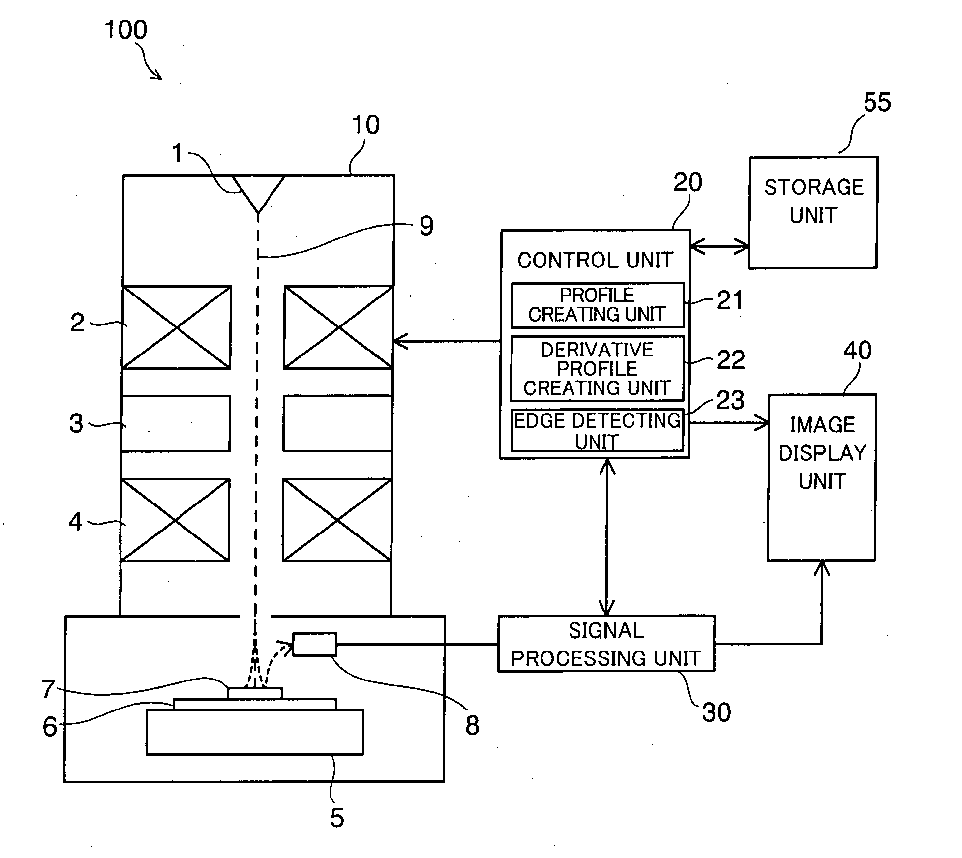
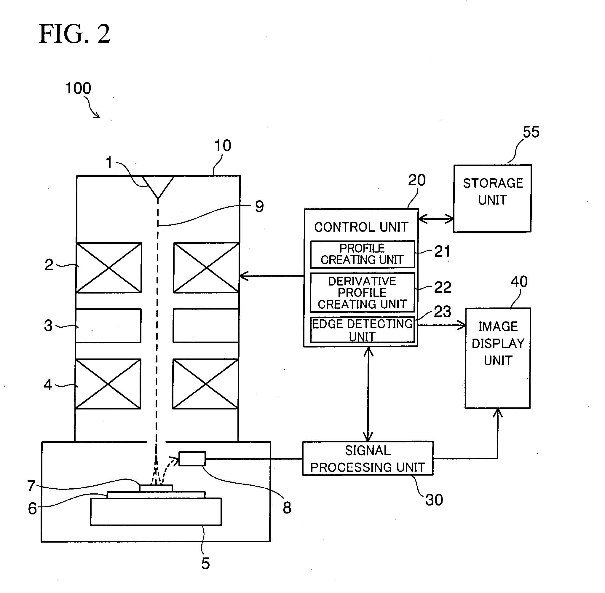
[0034]FIG. 2 is a block diagram of a scanning electron microscope according to an embodiment of the present invention.

[0035] This scanning electron microscope 100 essentially includes an electron sc...


PUM


Abstract

A pattern measurement apparatus includes a line profile creating unit for creating a line profile of a pattern formed on a sample by scanning with a charged particle beam, a derivative profile creating unit for creating a second derivative profile by differentiating twice the line profile, and an edge detecting unit for judging whether an edge in the pattern is a rising edge or a falling edge by use of two peak positions and two peak values appearing in the vicinity of an edge position of the pattern obtained from the second derivative profile. Assuming that the two peak positions appearing in the vicinity of the edge position of the pattern obtained from the second derivative profile are defined as X1 and X2, X2 being larger than X1, the edge detecting-unit judges that the edge is a rising edge when a signal amount in the peak position X1 is larger than a signal amount in the peak position X2.

Description

CROSS-REFERENCE TO RELATED APPLICATIONS [0001] This application is based on and claims priority of Japanese Patent Applications No. 2006-090290 filed on Mar. 29, 2006, and No. 2007-040858 filed on Feb. 21, 2007, the entire contents of which are being incorporated herein by reference. BACKGROUND OF THE INVENTION [0002] 1. Field of the Invention [0003] The present invention relates to a measurement apparatus and a measuring method for a pattern using a charged particle beam. More specifically, the present invention relates to a pattern measurement apparatus and a pattern measuring method capable of distinguishing between lines and spaces provided at even intervals in a spaced line-and-space pattern. [0004] 2. Description of the Prior Art [0005] Measurement using a scanning electron microscope has heretofore been applied to a line-width measuring method of a pattern. Here, a scanning electron microscope is configured to scan an electron beam scanning range by irradiating incident elect...

Claims


Application Information

Patent Timeline
Patent Type & Authority Applications(United States)
IPC IPC(8): G01B15/04
CPCG01B15/04G06T2207/10061G06T7/0083G01N23/227G06T7/12H01L22/00
Inventor MATSUMOTO, JUN
Owner ADVANTEST CORP
Why Eureka
Try Eureka