Maritime device for producing electric power

a technology of electric power and electric power, which is applied in the direction of motors, engine working fluids, engine fuctions, etc., can solve the problems of large error in calculated power, difficult and uncertain task of accurate assessment of eolic resources, and difficult to measure accurately eolic potentials

Inactive Publication Date: 2013-01-08
MARTINEZ MARDONES JORGE ALFONSO
View PDF11 Cites 0 Cited by
  • Summary
  • Abstract
  • Description
  • Claims
  • Application Information

AI Technical Summary

Benefits of technology

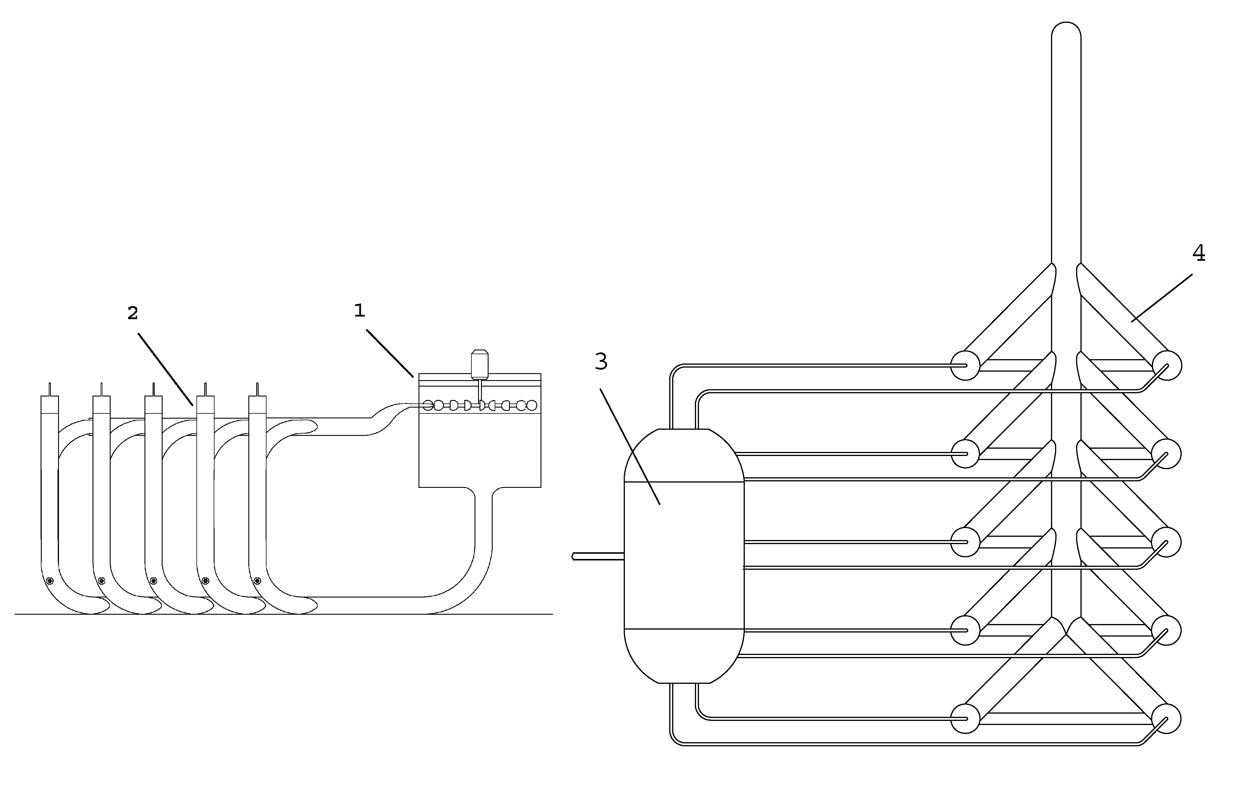
[0001]The present invention relates to energy generation from the conversion of the energy available in natural resources as ocean waves or wind. Specifically, it aims at optimizing plant factors associated with renewable energy generation, which are affected by the irregularities of natural resource energy availability, varying over periods of time and magnitudes of energy which are discontinuous and difficult to predict. Such optimization is possible due to the disposal of equipment capable of rectifying the irregularities of energy harness to deliver such energy by means of steady fluid flows, and harness energy as compressed air in order to regulate it, thus increasing supply guarantee.

Problems solved by technology

Like ocean swell, wind is a random resource in nature and thus, the accurate assessment of the eolic resource is a difficult and uncertain task.
Over short distances the colic power may vary by one order of magnitude.It is difficult to measure accurately the eolic potential.
The colic power is proportional to the cube of wind speed which means that a small error in its measurement leads to bigger error in the calculated power.
An error of 10% in wind speed measure implies a 33% error in the calculated eolic power.This means that the security of the eolic resource is low, and thereby the plant factor associated with eolic-type generating stations as well as those using ocean waves, is around 30% at the most.
1. According to Betz's law, the energy efficiency can be up to 60% at the most, since to make blades turn there must be a certain outgoing wind speed behind the blades, which is lower than the incoming wind speed that blades encounter. Therefore, the energy used is only the energy from the difference between the incoming wind speed and the outgoing wind speed from the blades.
2. The system operates until a certain range of maximum wind speed since beyond this limit generator hub and blades would be damaged.
3. Energy generation is produced only if there is wind available.
4. The generation system is dimensioned for a generation capacity or rated power close to the maximum possible wind speed within a range set in 2 to avoid wasting periods of high speed. Therefore, there is an increase in the cost with regard to the final use of the resource.
Secondly, it solves the cost issues associated with harnessing renewable energies, since nowadays these costs can not compete on equal terms with conventional energy generating stations.

Method used


Image

  • Maritime device for producing electric power
  • Maritime device for producing electric power
  • Maritime device for producing electric power

Examples


first embodiment

[0043]As stated before, the energy accumulator and rectifier equipment is fed by compressed air, in a first embodiment, from a maritime device by means of a motion produced by waves.

[0044]With reference to FIGS. 4 and 5, the marine device is defined by a floating pontoon (9) with articulated arm (11), an air cylinder (or piston), and a breasting system which consists of (10) mooring dolphins and breasting dolphins.

[0045]Its operation consists of a floating pontoon (9) which by following wave motion generates an ascending and descending vertical displacement of an articulated arm (11) attached to this pontoon. This arm comprises a ball socket end secured to a pile structure (mooring dolphins) and the other end is mounted on a floating pontoon (9) with its end trapped in a ring attached to the pontoon, which enables free movements thereon, with the exception of the ascending and descending motion.

[0046]This motion is used for the ball socket arm to activate a piston inside the cylinde...

second embodiment

[0048]According to the invention, the energy accumulating equipment can operate in conjunction with an eolic energy harnessing apparatus. With reference to FIGS. 7 y 8, such apparatus consists of three main elements. A sail or flag (15), vertically arranged and facing wind with vertical axis which crosses the sail and make it pivot thereon, a vertical screen (17), parallel to the sail and secured by its support and an air piston (16) which generates compressed air by sail or flag motion.

[0049]The sail and the axis (15) are arranged close to the vertical screen (17), so that when wind strikes both structures it brings the sail close to the screen until closing wind passing and then move the sail away an thereby, the sail is made to flap as a flag does with the wind.

[0050]The sail is secured to a ball socket arm of an air piston which through continuous sail motion generates compressed air which is transferred to the aforementioned hydraulic device accumulator. In order to follow the ...


PUM


Abstract

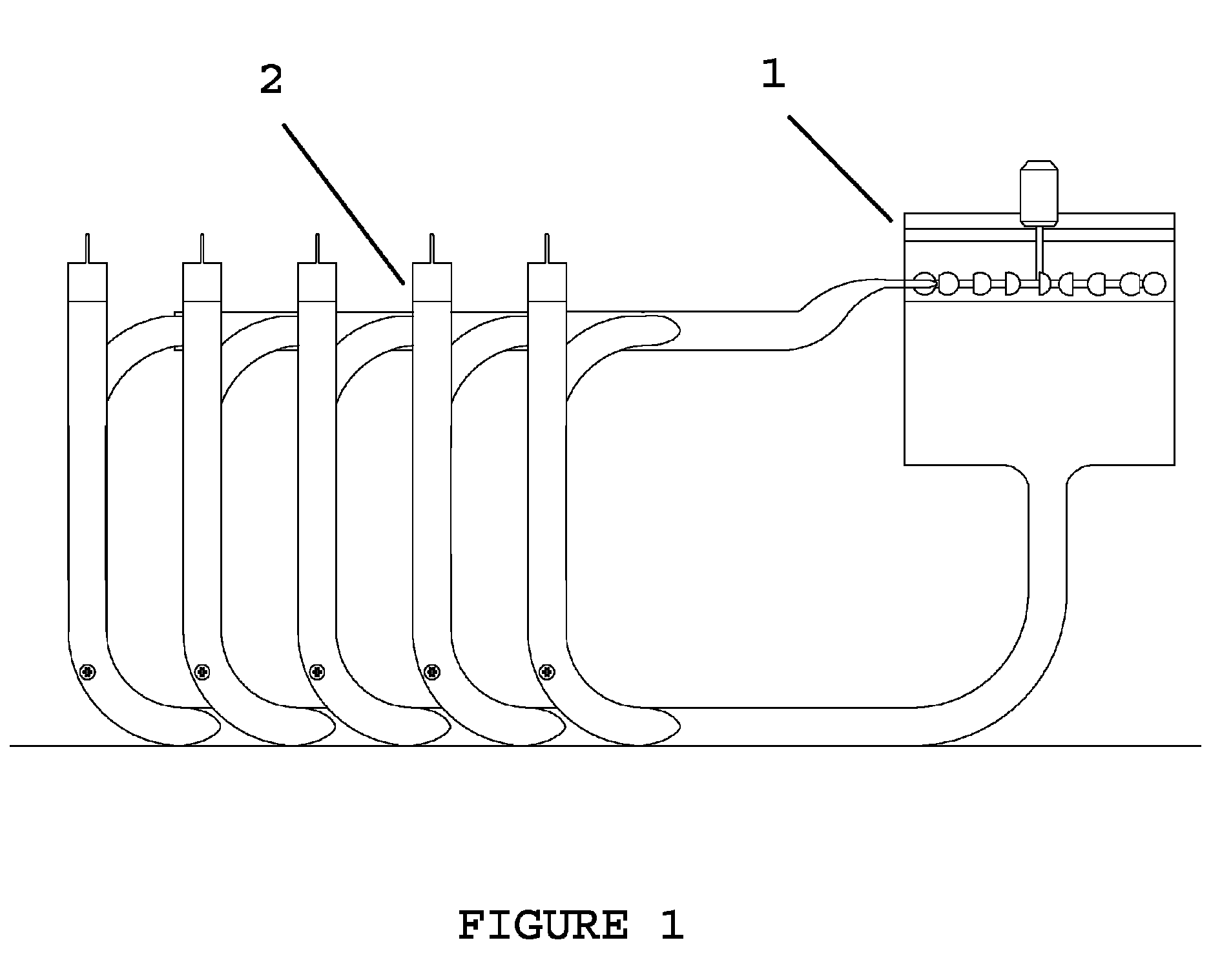
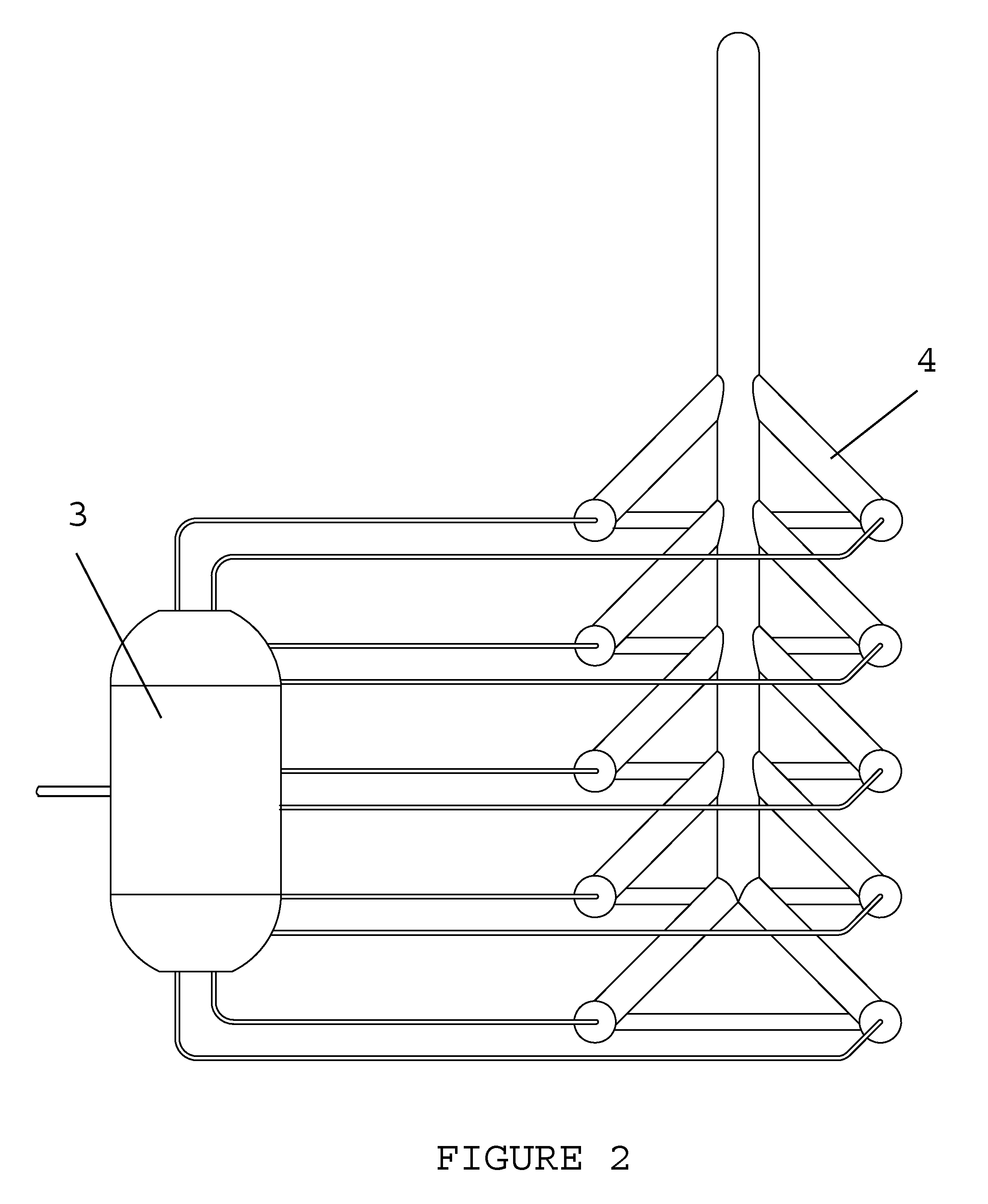
An energy accumulator and rectifier equipment for converting and generating renewable energy from ocean waves and winds, which includes a storage tank or compressed air accumulator, a series of vertical tubes filled with non-compressible fluid so that it can displace movable elements, forming a group, wherein each group is in connection with another similar group at both the upper level and the lower level by means of a fluid circulation pipes and by means of a pipe of smaller diameter, at the upper and lower portion, for air circulation, and wherein the fluid circulation pipes of every group are attached to a common pipe at the upper level which conveys the fluid toward a turbine-generator to produce electricity and a common pipe at the lower level to recirculate fluid toward the cylinders.

Description

[0001]The present invention relates to energy generation from the conversion of the energy available in natural resources as ocean waves or wind. Specifically, it aims at optimizing plant factors associated with renewable energy generation, which are affected by the irregularities of natural resource energy availability, varying over periods of time and magnitudes of energy which are discontinuous and difficult to predict. Such optimization is possible due to the disposal of equipment capable of rectifying the irregularities of energy harness to deliver such energy by means of steady fluid flows, and harness energy as compressed air in order to regulate it, thus increasing supply guarantee.[0002]The energy harnessing and rectifying equipment of the present invention is used in two alternative embodiments. The first embodiment consists of maritime device to harness power from waves and transfer it to the hydraulic device to generate electric power. And the second similar to the first...

Claims


Application Information

Patent Timeline
Patent Type & Authority Patents(United States)
IPC IPC(8): F03B13/10
CPCF03B13/1815F03D3/0436F03D9/028F03D9/001F03D9/025F03B13/24F03B13/266F03B17/025F05B2210/18F05B2240/211F05B2260/406Y02E10/38Y02E10/74Y02E60/15Y02E10/28Y02E10/20Y02E60/17F03D9/14F03D9/17F03D9/28Y02E10/30Y02E10/72Y02E60/16Y02E70/30
Inventor MARTINEZ MARDONES, JORGE ALFONSO
Owner MARTINEZ MARDONES JORGE ALFONSO
Why Eureka
Try Eureka