
Swing hinge apparatus of portable terminal

a portable terminal and hinge technology, applied in the field of portable terminals, can solve the problems of limited miniaturization of the portable terminal, difficult to secure a distance between the transmitter and the receiver, and limitations in the miniaturization of the flip-type portable terminal

Active Publication Date: 2008-01-24
SAMSUNG ELECTRONICS CO LTD
View PDF13 Cites 5 Cited by
  • Summary
  • Abstract
  • Description
  • Claims
  • Application Information

AI Technical Summary

Benefits of technology

[0013]An aspect of the present invention is to address the above-mentioned problems and / or disadvantages and to provide at least the advantages described below. Accordingly, an aspect of the present invention is to provide a swing hinge apparatus of a portable terminal, by which a pair of housings can be assembled with each other in a stable manner.
[0014]Another aspect of the present invention is to provide a swing hinge apparatus of a portable terminal, by which structural stability is obtained and costs for manufacturing can be reduced.
[0015]Another aspect of the present invention is to provide a swing hinge apparatus of a portable terminal in which manufacturing costs are inexpensive, an open / close operation is convenient, and risk of breakdown is decreased.
[0016]In accordance with an aspect of the present invention, a swing hinge apparatus of a portable terminal is provided. In the swing hinge apparatus, a pair of housings is rotatably assembled while facing each other. The swing hinge apparatus includes a lower casing mounted and fixed to a first housing from among the pair of housings, a cam member mounted and fixed to a second housing from among the pair of housings and rotatably received in the lower casing, a guide groove formed on the lower casing and extending along a circumference, and a guide protrusion formed on a first surface of the cam member and moving along the guide groove according to rotation of the cam member, wherein both ends of the guide protrusion have inclined outer walls, both ends of the guide groove have inclined inner walls, and the guide protrusion is engaged with one of the inclined inner walls of the both ends of the guide groove, so as to limit a range of rotation of the cam member.
[0017]In accordance with an aspect of the present invention, the outer walls of both ends of the guide protrusion and the inner walls of both ends of the guide groove are inclined so as to limit a range of rotation of the cam member, such that impact occurring at the moment when the rotation of the cam member stops can be reduced.

Problems solved by technology

A keypad used as the data input / output unit is always exposed to the outside and may result in the malfunction thereof.
Further, there is limitation in the miniaturization of the portable terminal because it is difficult to secure a distance between the transmitter and receiver.
However, there is also a limitation in the miniaturization of the flip type portable terminal because it is difficult to secure a distance between the transmitter and the receiver.
However, the swing-type portable terminals and the rotary-type portable terminals, or the sliding-folding portable terminals and the folding-swing portable terminals have difficulty in obtaining structural stability, so that there is a limitation on releasing to the market as products.
Further, due to the difficulty in obtaining the structural stability, there arises a problem in increasing costs for manufacturing a real product.
Furthermore, it is difficult to control a stop position of housings in a portable terminal that is opened / closed by a swing operation, users experience an inconvenience in a portable terminal opened / closed in a passive manner, the cost for manufacturing is increased in a portable terminal automatically opened / closed by using a motor and the like, and there is a risk of breakdown at the moment of stopping rotation because a spring is used in a portable terminal opened / closed semi-automatically.

Method used


Image

  • Swing hinge apparatus of portable terminal
  • Swing hinge apparatus of portable terminal
  • Swing hinge apparatus of portable terminal

Examples


Embodiment Construction

[0029]The following description with reference to the accompanying drawings is provided to assist in a comprehensive understanding of exemplary embodiments of the present invention as defined by the claims and their equivalents. It includes various specific details to assist in that understanding but these are to be regarded as merely exemplary. Accordingly, those of ordinary skill in the art will recognize that various changes and modifications of the embodiments described herein can be made without departing from the scope and spirit of the invention. Also, descriptions of well-known functions and configurations will be omitted for clarity and conciseness.

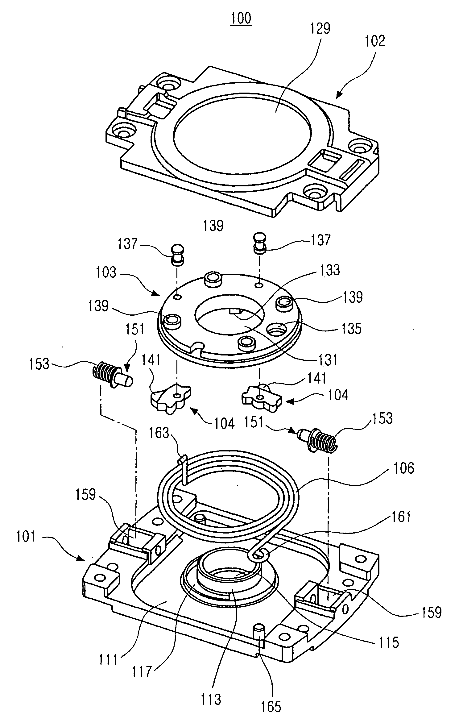
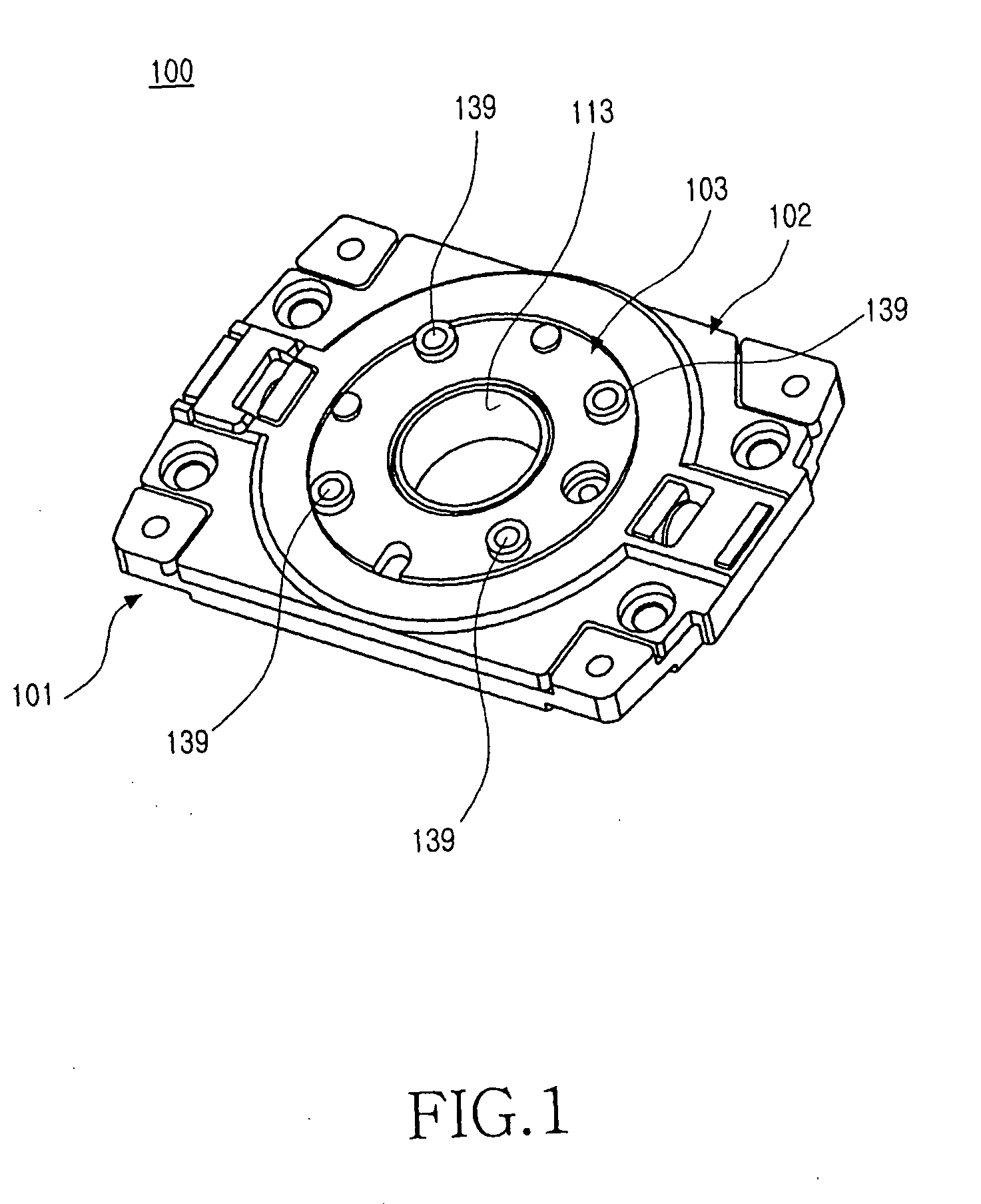
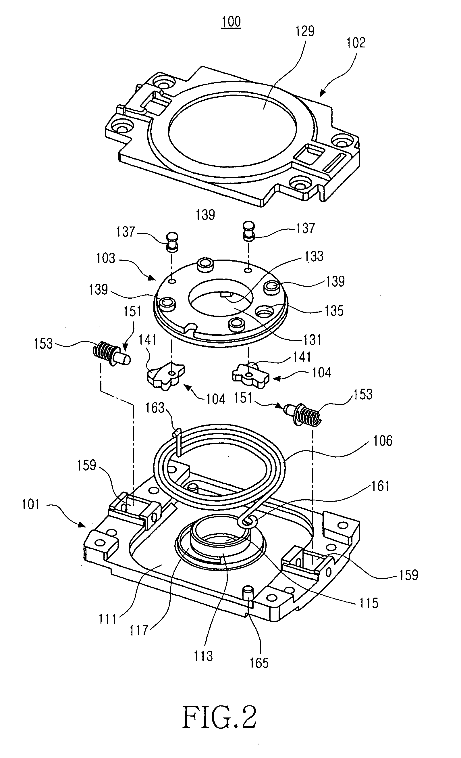
[0030]As shown in FIGS. 1 and 2, a swing hinge apparatus 100 of a portable terminal has a lower casing 101 with which a cam member 103 is rotatably assembled, and a guide groove 117 formed on the lower casing 101 and a guide protrusion 133 formed on the cam member 103 are used to limit a range of rotation of the cam member 103, a...


PUM


Abstract

A swing hinge apparatus of a portable terminal is provided. In the portable terminal, a pair of housings is rotatably assembled while facing each other. The swing hinge apparatus includes a lower casing mounted and fixed to a first housing from among the pair of housings, a cam member mounted and fixed to a second housing from among the pair of housings and rotatably received in the lower casing, a guide groove formed on the lower casing and extending along a circumference, and a guide protrusion formed on a first surface of the cam member and moving along the guide groove according to rotation of the cam member, wherein both ends of the guide protrusion have inclined outer walls, both ends of the guide groove have inclined inner walls, and the guide protrusion is engaged with one of the inclined inner walls of the both ends of the guide groove, so as to limit a range of rotation of the cam member.

Description

PRIORITY[0001]This application claims the benefit under 35 U.S.C. §119(a) of a Korean utility model application filed in the Korean Industrial Property Office on Jul. 24, 2006 and assigned Serial No. 20-2006-0019978, and a Korean patent application filed in the Korean Industrial Property Office on Mar. 12, 2007 and assigned Serial No. 10-2007-0024065, the entire disclosures of each of which are hereby incorporated by references.BACKGROUND OF THE INVENTION[0002]1. Field of the Invention[0003]The present invention relates to a portable terminal. More particularly, the present invention relates to a swing hinge apparatus of a portable terminal, by which a pair of housings can be rotatably assembled while facing each other.[0004]2. Description of the Related Art[0005]In general, a portable terminal refers to a device used to provide wireless communication between users or between a user and a service provider using a mobile communication station and the like. Portable terminals are clas...

Claims


Application Information

Patent Timeline
Patent Type & Authority Applications(United States)
IPC IPC(8): E05F1/12
CPCH04M1/0227Y10T16/54028Y10T16/54044Y10T16/53888
Inventor LEE, DONG-YUPSONG, DONG-CHULLEE, SANG-HEON
Owner SAMSUNG ELECTRONICS CO LTD
Learn More