Ion source with recess in electrode

a technology of electrodes and ion sources, applied in the field of ion sources, can solve the problems of reducing the associated ion energy, limiting and less focused or otherwise less efficient ion beams, so as to reduce energy efficiencies, reduce energy consumption, and limit the overall energy efficiency of the ion sour

Inactive Publication Date: 2008-01-24
GUARDIAN GLASS LLC
View PDF19 Cites 31 Cited by
  • Summary
  • Abstract
  • Description
  • Claims
  • Application Information

AI Technical Summary

Benefits of technology

[0006]A circular or oval shaped conductive anode 25, electrically connected to the positive pole of electric power source 29, is arranged so as to at least partially surround magnet 23 and be approximately concentric therewith. Anode 25 may be fixed inside the housing by way of insulative ring 31 (e.g., of ceramic). Anode 25 defines a central opening therein in which magnet 23 is located. The negative pole of electric power source 29 is grounded and connected to cathode 5, so that the cathode is negative with respect to the anode. Generally speaking, the anode 25 is generally biased positive by several thousand volts. Meanwhile, the cathode (the term “cathode” as used herein includes the inner and / or outer portions thereof) is generally held at ground potential. One example of a conventional ion source includes an anode having a flat top surface approximately 2 mm from the bottom of both the inner and outer cathodes.
[0007]The conventional ion beam source of FIGS. 1-3 is intended for the formation of a unilaterally directed tubular ion beam, flowing in the direction toward substrate 45. Substrate 45 may or may not be biased in different instances. The ion beam emitted from the area of slit / aperture 15 is in the form of a circle in the FIG. 2 embodiment and in the form of an oval (e.g., race-track) in the FIG. 3 embodiment. The conventional ion beam source of FIGS. 1-3 operates as follows in a depositing mode when it is desired that the ion beam deposit at least one layer on substrate 45. A vacuum chamber in which the substrate 45 and slit / aperture 15 are located is evacuated, and a depositing gas (e.g., a hydrocarbon gas such as acetylene, or the like) is fed into the interior of the source via aperture(s) 21 or in any other suitable manner. A maintenance gas (e.g., argon) may also be fed into the source in certain instances, along with or instead of the depositing gas. Power supply 29 is activated and an electric field is generated between anode 25 and cathode 5, which accelerates electrons to high energy. Anode 25 is positively biased by several thousand volts, and cathode 5 is at ground potential as shown in FIG. 1. Electron collisions with the gas in, and / or proximate to, aperture / slit 15 leads to ionization and a plasma is generated. “Plasma” herein means a cloud of gas including ions of a material to be accelerated toward substrate 45. The plasma expands and fills (or at least partially fills) a region including slit / aperture 15. An electric field is produced in slit 15, oriented in the direction substantially perpendicular to the transverse magnetic field, which causes the ions to propagate toward substrate 45. Electrons in the ion acceleration space in and / or proximate to slit / aperture 15 are propelled by the known E×B drift in a closed loop path within the region of crossed electric and magnetic field lines proximate to slit / aperture 15. These circulating electrons contribute to ionization of the gas (the term “gas” as used herein means at least one gas), so that the zone of ionizing collisions extends beyond the electrical gap between the anode and cathode and includes the region proximate to slit / aperture 15 on one and / or both sides of the cathode 5. For purposes of example, consider the situation where a silane and / or acetylene (C2H2) depositing gas is / are utilized by the ion source of FIGS. 1-3 in a depositing mode. The silane and / or acetylene depositing gas passes through the gap between anode 25 and cathode 5.
[0008]Unfortunately, the ion source of FIGS. 1-3 suffers several drawbacks. For example, conventional ion sources have small zones in which the ions can accelerate, thus limiting the overall energy efficiency of the ion source. Lower energy efficiencies may decrease the associated ion energies, which is not desirable in certain instances. The ions may tend to drift, potentially resulting in a less focused or otherwise less efficient ion beam. Also, the depth to which ions can penetrate the target substrate, if desired, may be limited by a lower ion energy.
[0009]Thus, it will be appreciated that there exists a need in the art for an ion source that overcomes one or more of the aforesaid problems.

Problems solved by technology

Unfortunately, the ion source of FIGS. 1-3 suffers several drawbacks.
For example, conventional ion sources have small zones in which the ions can accelerate, thus limiting the overall energy efficiency of the ion source.
Lower energy efficiencies may decrease the associated ion energies, which is not desirable in certain instances.
The ions may tend to drift, potentially resulting in a less focused or otherwise less efficient ion beam.
Also, the depth to which ions can penetrate the target substrate, if desired, may be limited by a lower ion energy.

Method used


Image

  • Ion source with recess in electrode
  • Ion source with recess in electrode
  • Ion source with recess in electrode

Examples


Embodiment Construction

[0022]Referring now more particularly to the accompanying drawings in which like reference numerals indicate like parts throughout the several views.

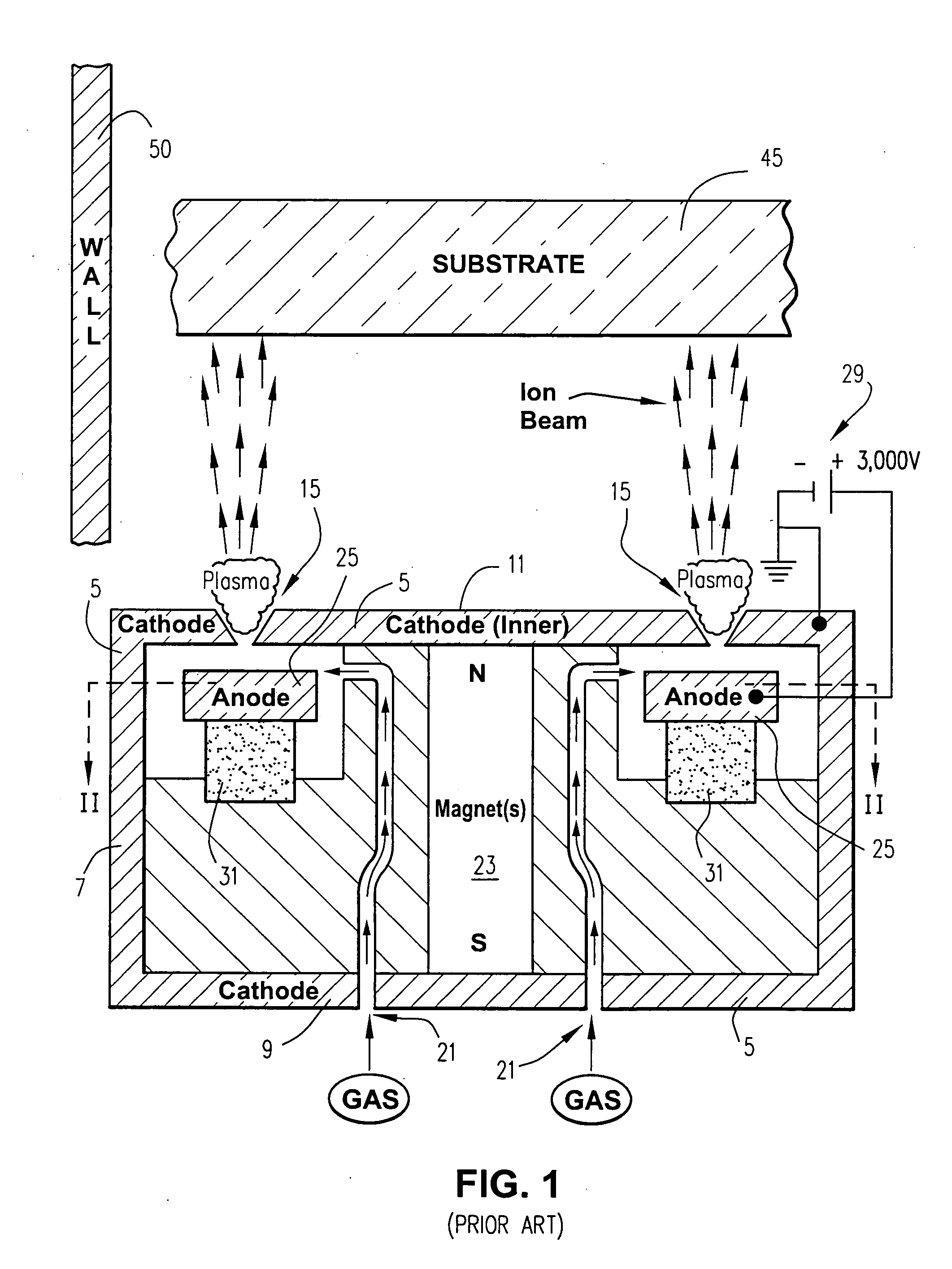
[0023]FIG. 4 is a cross sectional view of a cold cathode closed-drift ion source according to an example embodiment of this invention. The example embodiment shown in FIG. 4 functions similarly in many respects to the conventional ion source depicted with reference to FIGS. 1-3, and for this reason like references numerals are used in FIGS. 1-5.

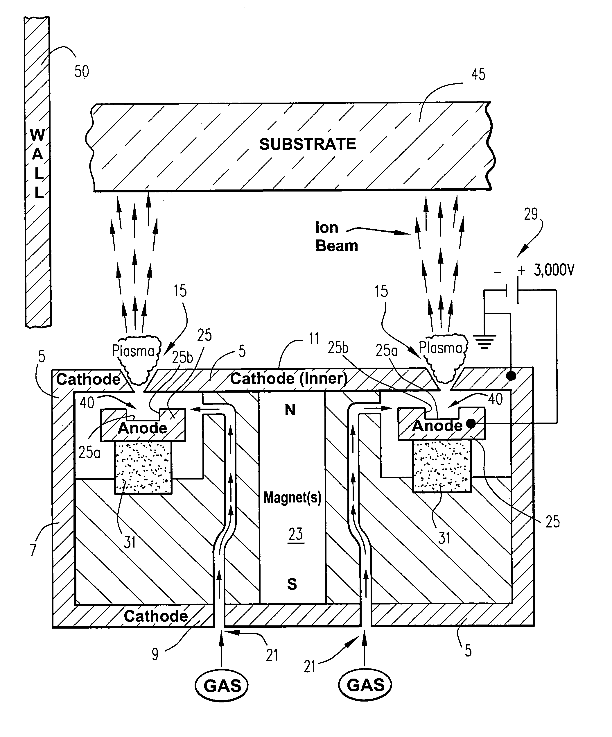
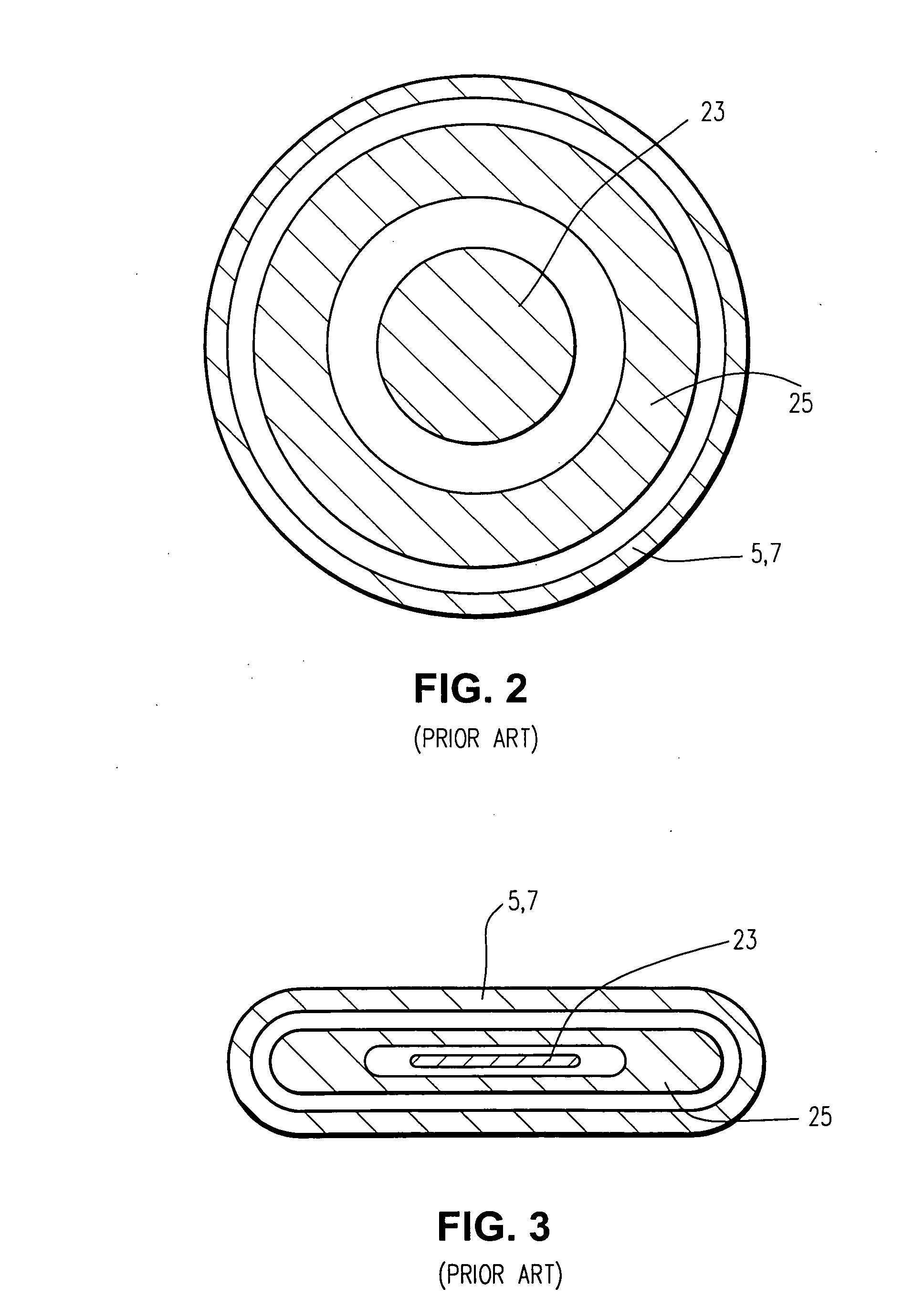
[0024]In the FIG. 4 example embodiment ion source, the slit / aperture (or discharge gap) 15 is formed in the cathode 5, so that the cathode has inner and outer portions as shown in the figure. Anode 25 is located below the cathode 5 and / or below the discharge gap or slit 15 defined therein. As shown in FIGS. 2-3, the anode 25 may be circular, oval, or otherwise shaped as viewed in a top-cross-sectional perspective in different example embodiments of this invention; and the discharge gap or slit 15...


PUM

PropertyMeasurementUnit
angleaaaaaaaaaa
angleaaaaaaaaaa
depthaaaaaaaaaa

Abstract

An ion source capable of generating and/or emitting an ion beam which may be used to deposit a layer on a substrate or to perform other functions is provided. The ion source includes at least one anode and at least one cathode. In certain example embodiments, the anode may have a recess formed therein in which ions to be included in the ion beam may accelerate. Walls of the recess optionally may be insulated using, for example, ceramic. One or more holes may be provided to allow a supply of gas to flow into the recess, and those holes optionally may be tapered such that they narrow towards the recess. Thus, certain example embodiments produce an ion source having a higher energy efficiency (e.g., having increasing ion energy).

Description

FIELD OF THE INVENTION[0001]The example embodiments herein relate to an ion source for generating an ion beam (diffuse, focused, or collimated). In certain example embodiments of this invention, an extended acceleration zone is created by forming a recess in an electrode (e.g., anode and / or a cathode) of the ion source.BACKGROUND AND SUMMARY OF EXAMPLE EMBODIMENTS OF THE INVENTION[0002]An ion source is a device that causes gas molecules to be ionized and then accelerates and emits the ionized gas molecules and / or atoms in a beam towards a substrate. Such an ion beam may be used for various purposes, including but not limited to cleaning a substrate, activation, polishing, etching, and / or deposition of thin-film coatings / layer(s). Example ion sources are disclosed, for example, in U.S. Pat. Nos. 7,030,390; 6,988,463; 6,987,364; 6,815,690; 6,812,648; and 6,359,388; the disclosures of which are all hereby incorporated herein by reference.[0003]FIGS. 1-2 illustrate a conventional cold-c...

Claims


Application Information

Patent Timeline
Patent Type & Authority Applications(United States)
IPC IPC(8): C23C16/00
CPCH01J27/024H01J2237/31H01J37/08H01J27/143
Inventor MURPHY, NESTOR P.
Owner GUARDIAN GLASS LLC
Why Eureka
Try Eureka