Grommet and forming method for the grommet

a technology of forming method and grommet, which is applied in the direction of manufacturing tools, transportation and packaging, and isolating bodies, etc., can solve the problems of reducing the gripping force, difficult to expand the grommet to the required size, and easy flexing of the tubular portion, so as to reduce the center core, increase the gripping force of the grommet against the car body panel, and easy to flex

Active Publication Date: 2008-01-24
SUMITOMO WIRING SYST LTD
View PDF5 Cites 23 Cited by
  • Summary
  • Abstract
  • Description
  • Claims
  • Application Information

AI Technical Summary

Benefits of technology

[0012] The present invention is provided considering the above-described problems. A purpose of the present invention is to provide a grommet which includes an extended tubular portion that extends inside a funnel shaped portion, and ribs that project from the extended tubular portion, and are connected to the internal surface of the funnel shaped portion. Such a grommet is configured to expand to a required size using an expander when a wire harness is inserted, and to easily remove a center core of a metal mold when the grommet is formed using the metal mold.
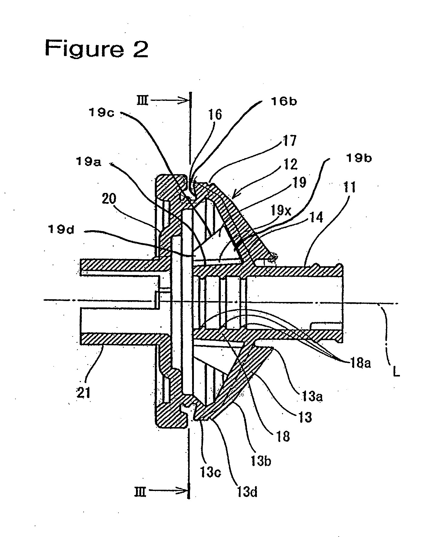
[0015] The grommet provides a reinforcement rib placed between the external circumferential surface of the extended tubular portion and the internal surface of the funnel shaped portion. Therefore, the extended tubular portion and the funnel shaped portion are reinforced. Among the plurality of ribs, except one type one rib, the type two ribs are linked to an external circumferential surface of the extended tubular portion via a thin linking portion. Therefore, the extended tubular portion can be expanded to a predetermined size using an expander when a wire harness is inserted. Efficiency of the wire harness insertion is thus improved. Further, because a thin linking portion is not provided to the one type one rib, and the type one rib is linked to the extended tubular portion via a thick portion, the type one rib prevents the extended tubular portion from turning up. Further, rather than a notch, grooves are provided between the extended tubular portion and the type two rib to form a thin linking portion. Therefore, when the grommet is formed using a metal mold which includes a center core, injected air in the process of center core removal can flows between the external circumferential surface of the center core and the internal surface of the funnel shaped portion of the grommet. Therefore, removal of the center core is easily achieved by expanding the grommet.
[0018] In the forming method of the grommet in the present invention, in the process of removing the center core from the grommet after the grommet is formed, air injected between the center core and the grommet flows more easily between the center core and internal surface of the grommet, at a location where a rib is provided on the external circumference of the extended tubular portion, where the type two rib is formed having the thick portion without grooves. Pressure of the air to be injected inside the grommet is adequately increased to expand the first grommet sufficiently so that removal of the center core can be performed easily.
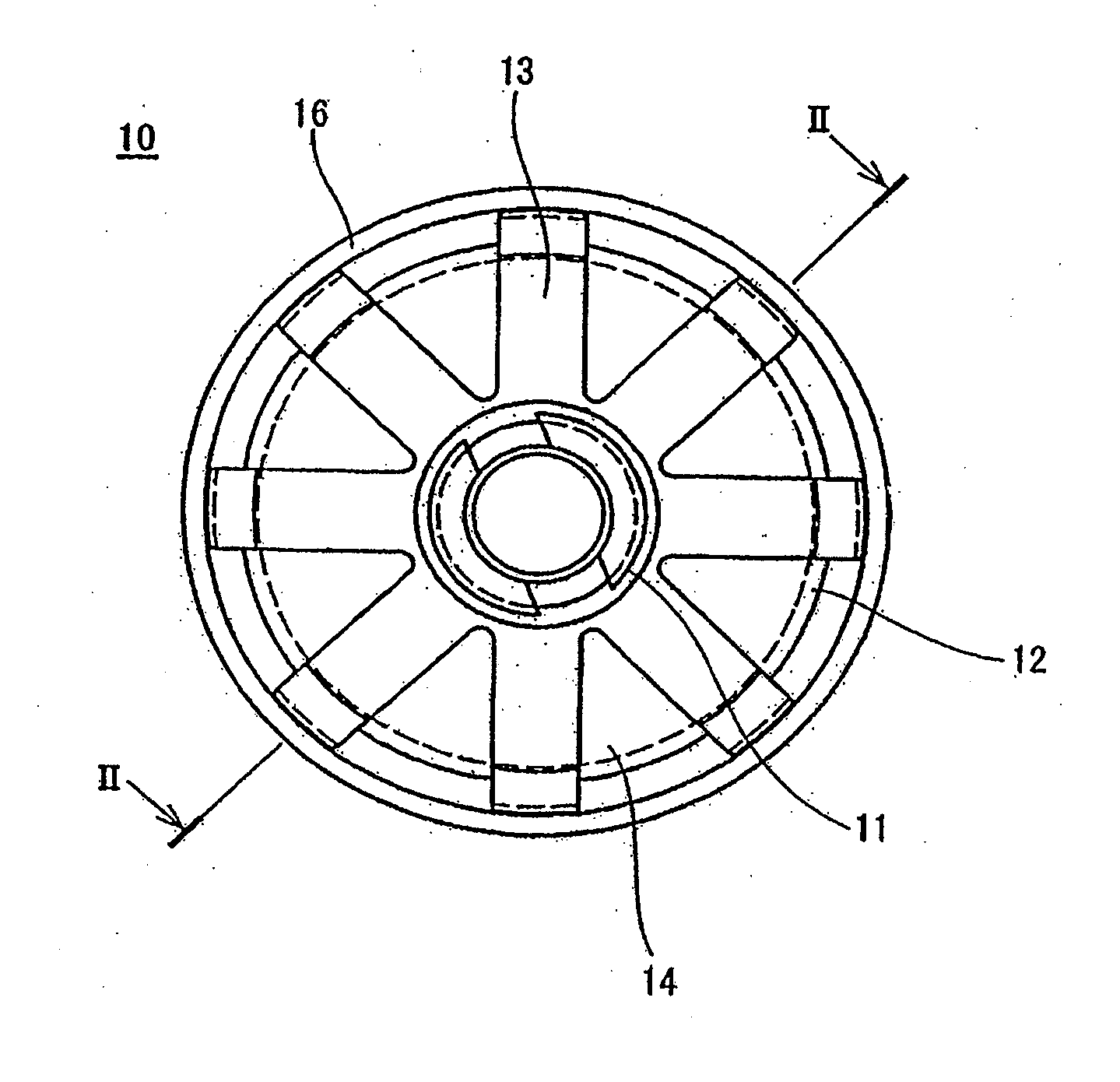
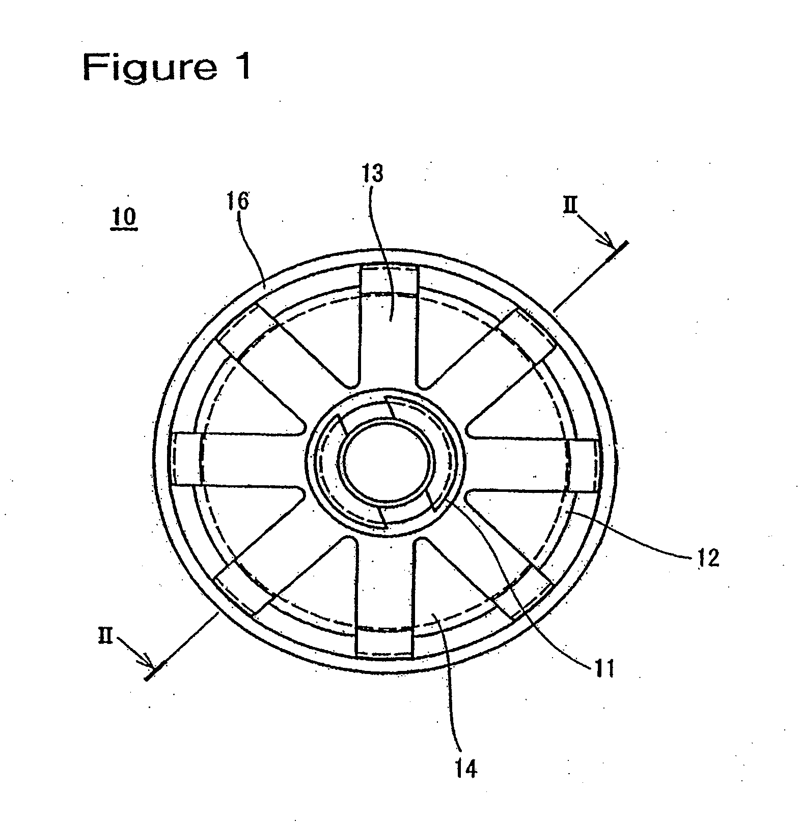
[0019] As is clear from the above explanation, according to the grommet of the present invention, providing the extended tubular portion projecting into the funnel shaped portion and the series of ribs between the extended tubular portion and the internal surface of the funnel shaped portion prevents the extended tubular portion from turning up, and secures the coherence between the extended tubular portion and the wire harness. Further, deformation of the body latch groove portion on the external circumferential surface of the funnel shaped portion is also prevented, and the gripping force of the grommet against the car body panel is increased. Furthermore, by providing the water sealing portion that seals the wire harness wires in the extended tubular portion, the water sealing portion is not placed in the tubular portion, which projects from the funnel shaped portion. Therefore, the wire harness can be easily flexed along with the tubular portion. Flexibility and wiring availability are thus improved. Moreover, the ribs are linked to the extended tubular portion via thin linking portions. Therefore, when the wire harness is inserted in the grommet, the extended tubular portion can be expanded without strain to the predetermined size by the fingers of the expander. The wire harness can be passed through the grommet smoothly.
[0020] In the forming process of the grommet of the present invention using the metal mold including upper, center and lower molds and the center core, the configuration of the series of ribs that are placed on the extended tubular portion and the internal surface of the funnel shaped portion is improved; one rib having no notch and the remaining ribs having a thin linking portion. Such improvements enable the grommet to expand by way of the injected air that flows onto the internal surface of the grommet in the process of the center core removal. In such structure, the center core can be smoothly removed from the grommet.

Problems solved by technology

As shown in FIG. 7, however, a problem arises when a wire harness is passed through the grommet 1.
Thus, it is difficult to expand the grommet to the required size.
However, without linking the rib 6 and the funnel shaped portion 2, deformation of the funnel shaped portion 2 cannot be controlled, which leads to a decrease of the gripping force when the grommet is attached to the car body panel.
Further, when the linking portion between the rib 6 and the extended tubular portion 5 is eliminated, reinforcement for the extended tubular portion becomes insufficient, which causes the following problems: the extended tubular portion may be turned up easily and the water sealing function deteriorates.
However, when the rib 6 is configured as shown in FIG. 8, a problem arises: when the grommet 1 is formed, its removal from a metal mold becomes difficult.

Method used


Image

  • Grommet and forming method for the grommet
  • Grommet and forming method for the grommet
  • Grommet and forming method for the grommet

Examples


Embodiment Construction

[0034] The particulars shown herein are by way of example and for purposes of illustrative discussion of the embodiments of the present invention only and are presented in the cause of providing what is believed to be the most useful and readily understood description of the principles and conceptual aspects of the present invention. In this regard, no attempt is made to show structural details of the present invention in more detail than is necessary for the fundamental understanding of the present invention, the description is taken with the drawings making apparent to those skilled in the art how the forms of the present invention may be embodied in practice. The following describes a preferred embodiment of the present invention with reference to the drawings. A grommet 10 is formed unitarily and in one piece, from a suitable material such as, for example, rubber or an elastomer. The grommet 10 includes a funnel shaped portion 12 which includes a conical surface having a flared ...


PUM

PropertyMeasurementUnit
thicknessaaaaaaaaaa
thicknessaaaaaaaaaa
thicknessaaaaaaaaaa

Abstract

A grommet is formed having a funnel shaped portion and a tubular portion linked to a small diameter end portion of the funnel shaped portion. The grommet is inserted to an aperture of a car body panel after a wire harness is passed through and attached to the funnel shaped portion and the tubular portion, and a body latch groove provided on the external circumferential surface of the funnel shaped portion is latched to the car body panel. An extended tubular portion is provided that projects from the tubular portion, and extends inside the funnel shaped portion. A plurality of ribs is provided on an external circumferential surface of the extended tubular portion. The ribs include type one ribs having grooves on both surfaces of an element linking the rib to the extended tubular portion, and a type two rib having no groove.

Description

CROSS-REFERENCE TO RELATED APPLICATIONS [0001] The present disclosure relates to subject matter contained in priority Japanese Patent Application No. 2006-197890, filed on Jul. 20, 2006, which is herein incorporated by reference in its entirety. BACKGROUND OF THE INVENTION [0002] 1. Field of the Invention [0003] The present invention relates to a grommet for mounting on a wire harness to be wired in automobiles, and a method of forming the grommet. [0004] 2. Description of Related Art [0005] It is known in the art to mount a grommet on a wire harness wired from an engine compartment to a passenger compartment of an automobile. Such a grommet is mounted to an aperture of a car body panel that separates a passenger compartment from an engine compartment of the automobile. The grommet protects the wire harness passing through the aperture and provides protection from water and dust, as well as sound insulation between the engine compartment and the passenger compartment. [0006] Several...

Claims


Application Information

Patent Timeline
Patent Type & Authority Applications(United States)
IPC IPC(8): H01B17/58
CPCB60R16/0222Y10T16/05H02G3/22
Inventor UCHIDA, YOSHIMIYONEZU, KOJIMATSUMOTO, MANABU
Owner SUMITOMO WIRING SYST LTD
Why Eureka
Try Eureka