Pneumatic grease applicator

Inactive Publication Date: 2008-01-24
LIH YANN INDAL
View PDF5 Cites 6 Cited by
  • Summary
  • Abstract
  • Description
  • Claims
  • Application Information

AI Technical Summary

Benefits of technology

[0011]Thus, the present invention is aimed to provide a grease applicator that is easy to operate for efficiently applying grease to mechanical parts.
[0012]The present invention is to provide a grease applicator that is pneumatically operable for uniformly and efficiently applying grease to bearings.
[0013]The present invention provides a grease applicator that is completely grease leakage-proof and is thus free of contamination caused by grease.
[0014]To realize the above objectives, in accordance with the present invention, there is provided a pneumatic grease applicator comprising a receptacle in which a retainer that forms a tubular axle selectively fit into a bearing to which grease is to be applied and a presser that defines a bore fit over the axle are movably received. The presser forms a top cavity in which a nozzle for coupling an external grease source is fixed. Grease is pneumatically supplied through the nozzle into the tubular axle and discharge through radially-extending holes defined in the axle to cover the bearing fit on the axle. An air vent is formed in the presser for pressure balance. Sealing members are provided between side wall of the receptacle and both the retainer and the presser to prevent leakage of grease.

Problems solved by technology

Since grease is a viscous substance, the application of grease to bearings is difficult, and often resulting in contamination of working site or the clothes and body of the worker by being unexpected or accidentally contacted by the workers' hands.
(A) The operation of the conventional grease applicator is based on the amount of grease fed in a grease receptacle 10a (see FIG. 1) of the applicator, and such an amount is limited due to the limited capacity of the receptacle.
Such repeated disengagement / engagement of the retainer and the presser 12a is quite likely to cause undesired contamination both inside and outside the receptacle 10a. Further, the requirement for frequent replenishment of grease makes it impossible to consecutively apply grease to a number of bearings.
The tubular axle 111a is thus often in a pressed condition, which makes the tubular axle 111a fatigue and thus easily broken.
This means a great waste of grease.
This often causes fatigue of the operator's hand and lowers the operation efficiency.

Method used


Image

  • Pneumatic grease applicator
  • Pneumatic grease applicator
  • Pneumatic grease applicator

Examples


Embodiment Construction

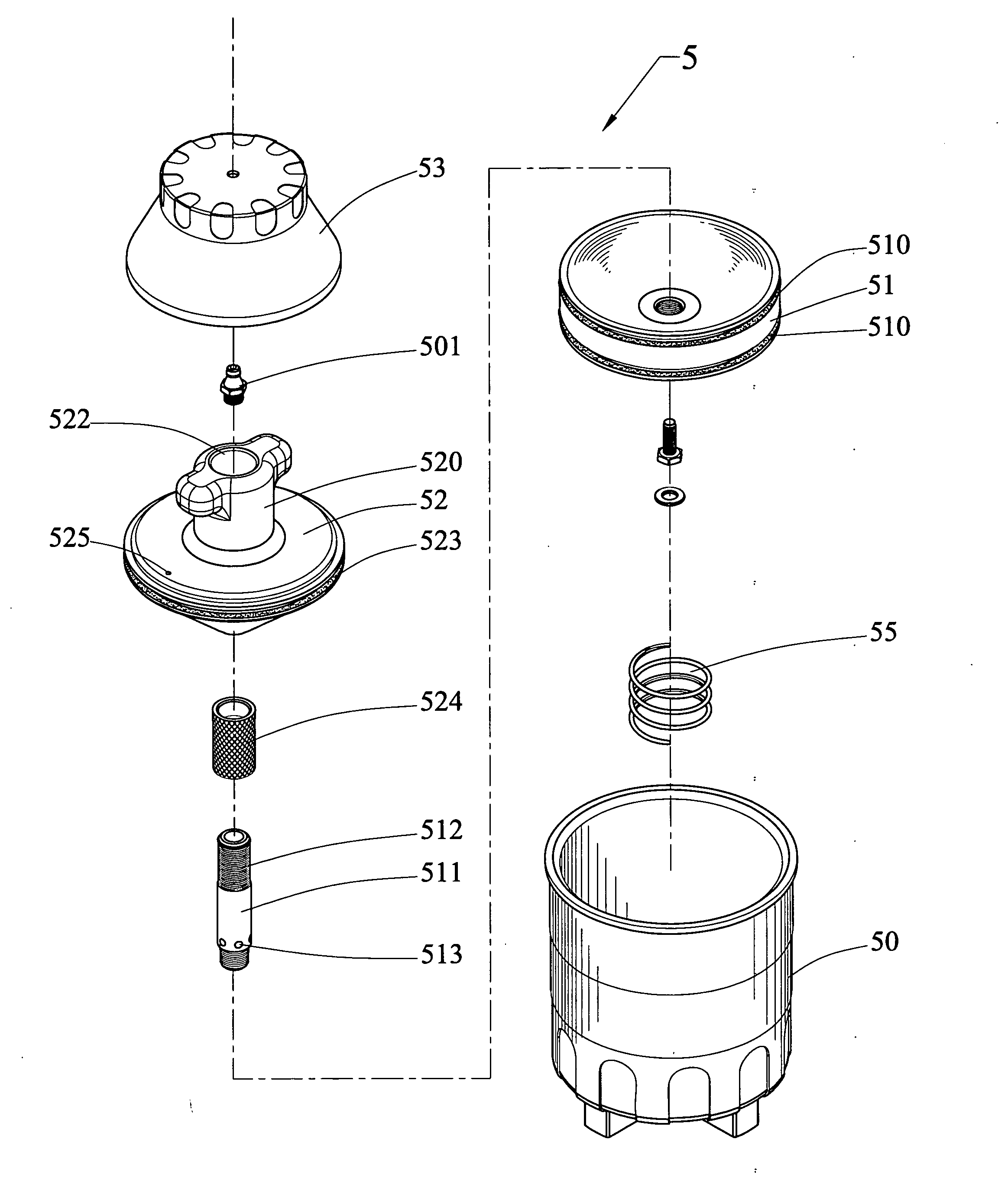
[0025]With reference to the drawings and in particular to FIGS. 3-6, a pneumatic grease applicator constructed in accordance with the present invention, generally designated with reference numeral 5, comprises a grease receptacle 50, a bearing retainer 51, a presser 52, and a dust cover 53. The receptacle 50 comprises a container having a top opening and a closed bottom. The bottom of the receptacle 50 defines an air vent passage 54.

[0026]The bearing retainer 51 is movably received in the receptacle 50 via the top opening and has a bottom face opposing and spaced from the closed bottom of the receptacle 50. A resilient member 55, such as a helical spring, is mounted to the bottom face of the bearing retainer 51 and is movable with the bearing retainer 51 inside the receptacle 50 to have a lower end of the resilient member 55 engaging the closed bottom of the receptacle 50. The retainer 51 also has an opposite top face in which a truncated conic recess (not labeled) having a flat cen...


PUM


Abstract

Disclosed is a pneumatic grease applicator includes a receptacle in which a retainer that forms a tubular axle selectively fit into a bearing to which grease is to be applied and a presser that defines a bore fit over the axle are movably received. The presser forms a top cavity in which a nozzle for coupling an external grease source is fixed. Grease is pneumatically supplied through the nozzle into the tubular axle and discharge through radially-extending holes defined in the axle to cover the bearing fit on the axle. An air vent is formed in the presser for pressure balance. Sealing members are provided between side wall of the receptacle and both the retainer and the presser to prevent leakage of grease.

Description

BACKGROUND OF THE INVENTION[0001]1. Field of the Invention[0002]The present invention relates generally to a grease applicator that is employed to apply grease to mechanical elements, such as a bearing, and in particular to a pneumatically operated grease applicator in which grease is supplied and driven to cover over the bearing by pneumatic force.[0003]2. The Related Art[0004]Industrial applications of bearings, for example heavy machinery, such as trucks and automobiles, require the bearings be uniformly coated with grease for lubrication purposes. Conventionally, the application of grease to bearings is done manually. In other words, workers apply grease to bearings by bear hands or hands with gloves. Since grease is a viscous substance, the application of grease to bearings is difficult, and often resulting in contamination of working site or the clothes and body of the worker by being unexpected or accidentally contacted by the workers' hands. Grease applicators are available ...

Claims


Application Information

Patent Timeline
IPC IPC(8): F16C1/24
CPCF16N2210/14F16N11/08
Inventor LIAO, PO LIN
Owner LIH YANN INDAL
Why Eureka
Try Eureka