Position Finding System For Locating The Position Of A Tool

Inactive Publication Date: 2008-01-24
C & E FEIN
View PDF6 Cites 25 Cited by
  • Summary
  • Abstract
  • Description
  • Claims
  • Application Information

AI Technical Summary

Benefits of technology

[0014] It is a third object of the present invention to disclose an improved system and method for locating the position of a tool by which safe and sufficiently exact position finding of a tool is rendered possible, even under conditions when line-of-sight view to base stations is obstructed.
[0036] This permits errors in the relative position finding to be detected and corrected, and the overall accuracy of the relative position finding system to be clearly improved.

Problems solved by technology

However, the inertial systems commonly used have only small working spaces due to constructional drift.
This means that any position finding performed over longer periods of times (more than 5 seconds) and longer distances (more than 50 centimeters) will lack the necessary accuracy.
When tightening screws in an assembly line for vehicles, defective screw connections have been encountered again and again because the exact coordination between screwdriver and bodyshell is not sufficiently verified.
As has been explained before, the use of inertial systems for relative position finding purposes does not provide sufficient accuracy over longer distances or times. On the other hand, free-field position finding systems can no longer be used for absolute determination of a position in cases where no direct connection to the outside, for determination of the position, can be ensured due to line-of-sight obstructions existing in the component.

Method used


Image

  • Position Finding System For Locating The Position Of A Tool
  • Position Finding System For Locating The Position Of A Tool
  • Position Finding System For Locating The Position Of A Tool

Examples


Embodiment Construction

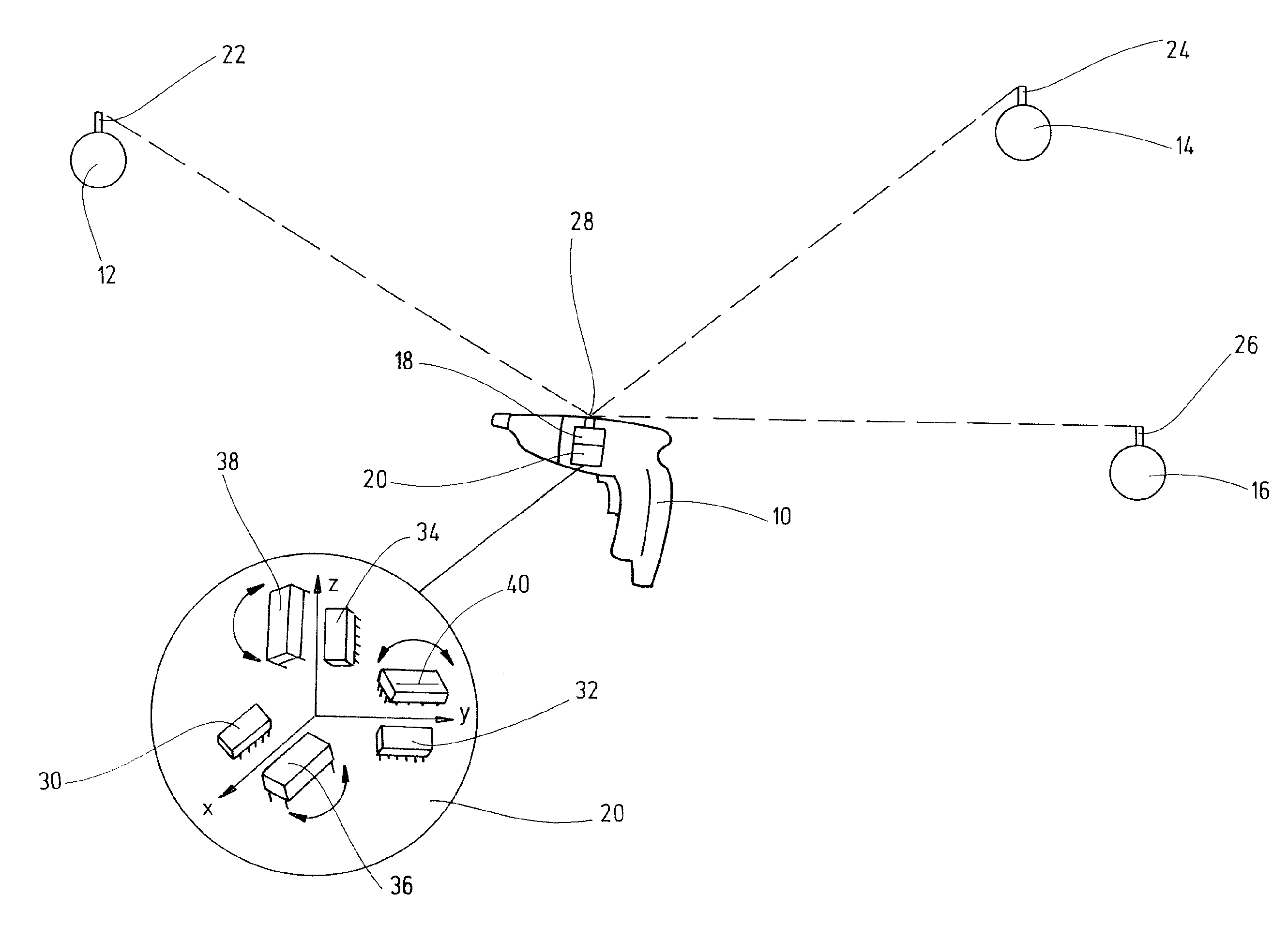
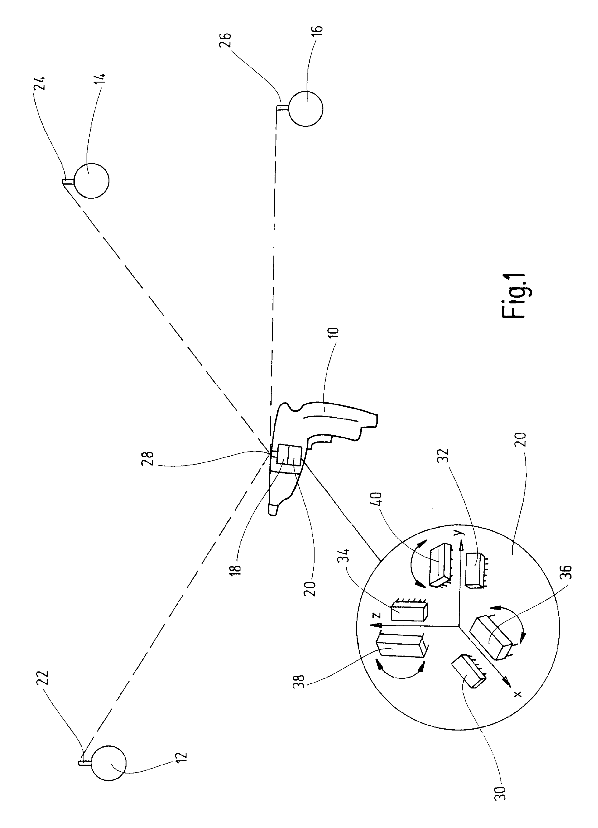
[0043]FIG. 1 shows a diagrammatic representation of a position finding system according to the invention which comprises a tool 10 in the form of a power screwdriver that is in direct communication contact with three base stations 12, 14, 16. The tool 10 comprises a radio module 18 and an inertial module 20 that are coupled one with the other. The radio module 18 is directly linked, via an antenna 28, with antennas 22, 24, 26 of external base modules 12, 14,16 the position of which is known.

[0044] The radio module 18 thus can determine the absolute position of the antenna 28 by propagation time measurements.

[0045] If positionally exact determination of the position of the tool 10 should be necessary, at least three antennas are required that should by in direct radio communication with the base stations in order to determine three points of the tool in space and, thus, the absolute position of the tool 10 in space.

[0046] For most of the applications it will, however, be sufficien...


PUM


Abstract

The invention provides a position finding system and a method for locating the position of a tool, in particular a hand-held screwdriver, wherein free-field position finding is performed for determining the absolute position of the tool and wherein relative position finding is performed for determining the relative position of the tool by tracking the movement of the tool relative to a known reference position, and combining the results with the result of the free-field position finding process for determining the position of the tool.

Description

CROSS-REFERENCE TO RELATED APPLICATIONS [0001] The present application claims priority of German patent application No. 10 2006 034 270.4 filed on a Jul. 18, 2006, the content of which is incorporated herein by reference. FIELD OF THE INVENTION [0002] The present invention relates to a position finding method and system for locating a tool, in particular a power screwdriver, more particularly a hand-held power screwdriver. BACKGROUND OF THE INVENTION [0003] Different methods for sensing the position of tools are known in the prior art. [0004] DE 199 01 334 A1 discloses a system for sensing the position of a hand-held tool comprising a computer and a sensor system, where the sensor system is located in or on or near the tool, where variations in the position of the tool are sensed by the sensor system, and where the locations of one or more possible working positions on an object to be worked are known and the position determined by a computer is compared with the possible working po...

Claims


Application Information

Patent Timeline
IPC IPC(8): G01B11/14G01B17/00G01S5/14G01S19/49
CPCG01S19/49G01S5/0027
Inventor SCHREIBER, ALFRED
Owner C & E FEIN
Why Eureka
Try Eureka