Heat exchanger assembly

Active Publication Date: 2008-01-31
MAHLE INT GMBH
View PDF40 Cites 27 Cited by
  • Summary
  • Abstract
  • Description
  • Claims
  • Application Information

AI Technical Summary

Benefits of technology

[0013]The heat exchanger assembly of the present invention provides a cost effective, flexible, and efficient solution for directing the heat exchange fluid in and out of the heat exchanger assembly. The insert directs the heat exchange fluid received from the inlet port through the first manifold through the flow tubes and out of the heat exchanger assembly through the outlet port. The inlet and outlet ports may be oriented and located at various locations to receive external plumbing connections connected to the heat exchanger assembly. The heat exchanger assembly has reduced manufacturing cost and may be configured to meet various inlet and outlet port requirements.

Problems solved by technology

While the external plumbing connections help to route the refrigerant to and from the heat exchanger assembly, the external plumbing connections are often complex, which increases cost and takes up space.
Specifically, the heat exchanger assemblies of the '248 patent are limited to one configuration of the inlet and outlet port location due to an extrusion process employed to form the outlet tank integral with one of the manifolds.
In addition, the internal outlet port must be properly located and made, which increases manufacturing costs of the heat exchanger assemblies.
The heat exchanger assemblies of the '248 patent are also made of many pieces, which further increases manufacturing costs.
The heat exchanger assemblies of the '407 patent are also extruded and made of many pieces, which increases manufacturing costs.
In addition, location of the inlet and outlet tanks limits the heat exchanger assemblies to one configuration.

Method used


Image

  • Heat exchanger assembly
  • Heat exchanger assembly
  • Heat exchanger assembly

Examples


Embodiment Construction

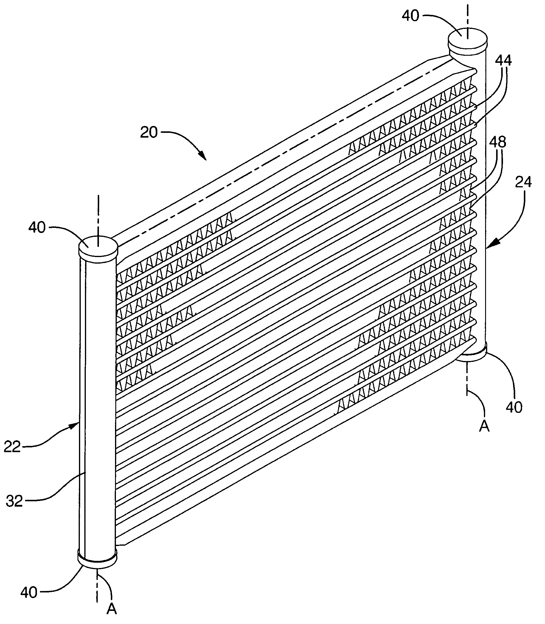
[0030]Referring to the Figures, wherein like numerals indicate corresponding parts throughout the several views, a heat exchanger assembly is shown generally at 20.

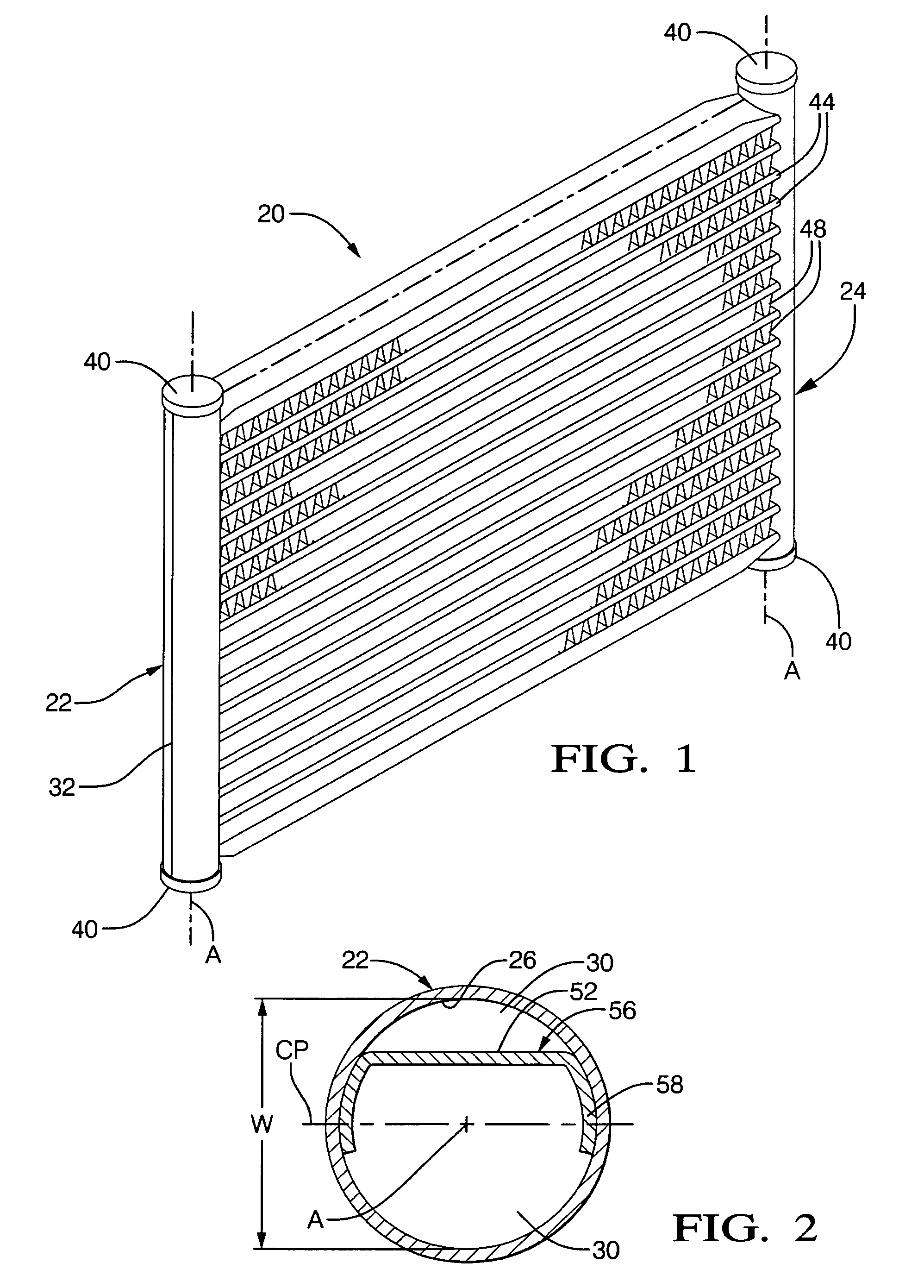
[0031]Referring to FIG. 1, a first embodiment of the heat exchanger assembly 20 is shown. The heat exchanger assembly 20 includes a first manifold 22 and a second manifold 24 spaced from the first manifold 22. The manifolds 22, 24 are spaced from and parallel to each other. Those of ordinary skill in the art appreciate that the manifolds 22, 24 may be nonparallel to each other. Reference to the first manifold 22 and the second manifold 24 is interchangeable in the description of the present invention.

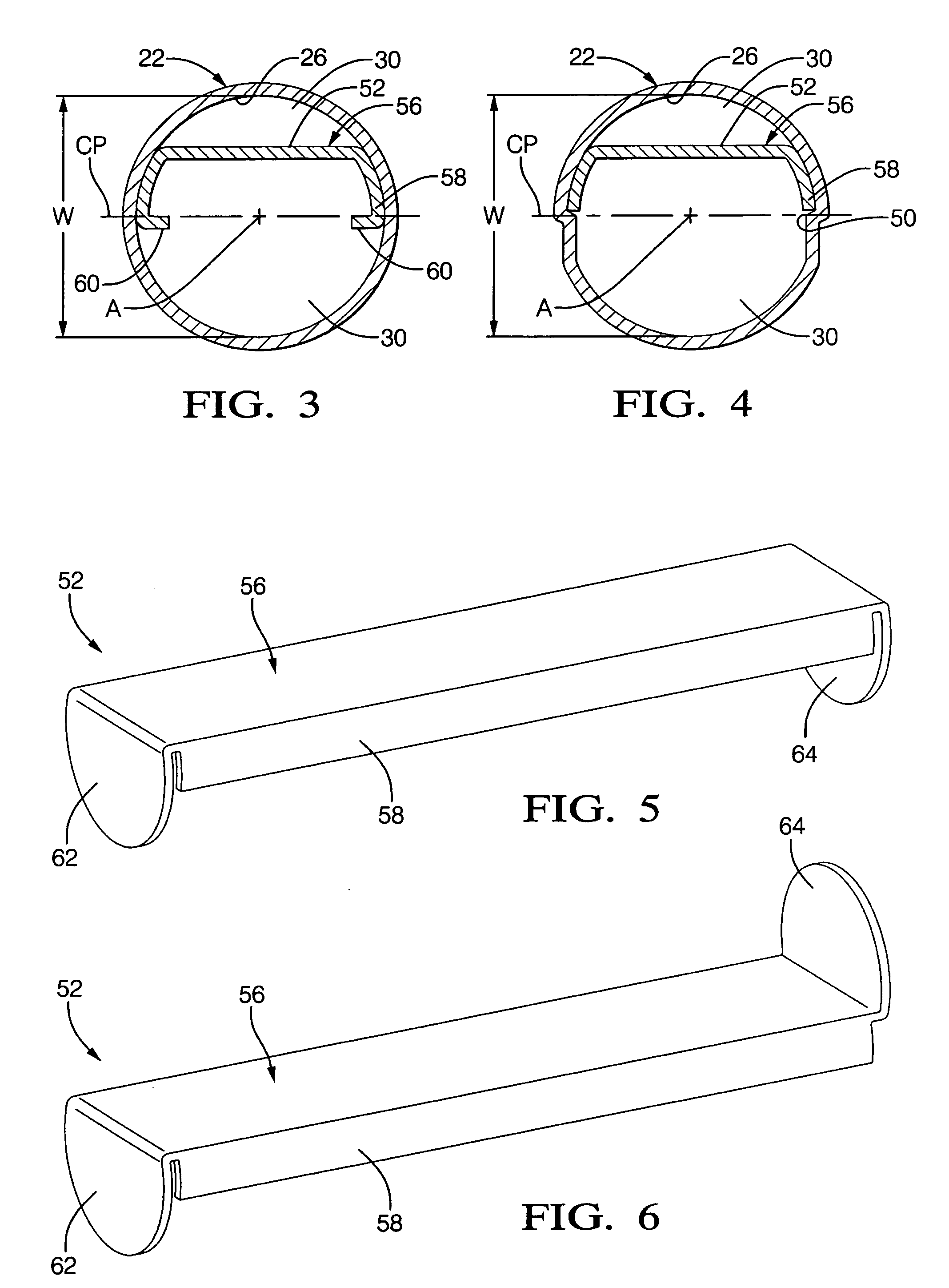
[0032]As best shown in FIGS. 10, 13, and 14, each of the manifolds 22, 24 includes a tubular wall 26 and a pair of manifold ends 28 spaced from each other defining a flow path 30. As best shown in FIGS. 11, 12, and 15, the flow path 30 extends between the manifold ends 28 of the first manifold 22. As best shown in FIGS. 2-4, ...


PUM


Abstract

A heat exchanger assembly includes a first and second manifold. Each of the manifolds includes a tubular wall and a pair of manifold ends spaced from each other defining a flow path. A plurality of flow tubes extend between the manifolds and are in fluid communication with the flow paths. An insert is slidably disposed in the flow path of the first manifold. The insert divides the flow path into a plurality of chambers. The chambers and the flow tubes cooperate to establish a plurality of flow passes. The flow passes are for directing a heat exchange fluid through the heat exchanger assembly. The chambers are useful for orienting and connecting plumbing connections at various locations along the manifolds.

Description

CROSS REFERENCE TO RELATED APPLICATION[0001]This application is a continuation-in-part of U.S. patent application Ser. No. 11 / 492,477 filed on Jul. 25, 2006, the advantages and disclosure of which are hereby incorporated by reference.BACKGROUND OF THE INVENTION[0002]1. Field of the Invention[0003]The present invention generally relates to a heat exchanger assembly. More specifically, the present invention relates to a heat exchanger assembly including an insert for directing a heat exchange fluid through the heat exchanger assembly.[0004]2. Description of the Related Art[0005]Heat exchanger assemblies such as evaporators and condensers are well known to those skilled in the art of thermal science. The heat exchanger assemblies may be used for vehicles, such as cars and trucks. The heat exchanger assemblies may also be used for buildings, such as homes and factories. The heat exchanger assemblies generally include a pair of spaced and parallel manifolds with a series of parallel flow...

Claims


Application Information

Patent Timeline
IPC IPC(8): F28F9/02
CPCF28D1/05375F28F9/0265F28F9/0207
Inventor BEAMER, HENRY EARLSOUTHWICK, DAVID A.
Owner MAHLE INT GMBH
Why Eureka
Try Eureka