Muffler having adjustable butterfly valve for improved sound attenuation and engine performance

a butterfly valve and muffler technology, applied in the field of improved mufflers, can solve the problems of inefficient muffler positioning, inability to adjust the conventional baffle, undesired operator to disassemble the muffler, etc., and achieve the effect of maximizing the sound level of the muffler, minimizing the muffler emitted by the muffler, and increasing horsepower

Inactive Publication Date: 2008-01-31
PACINI LARRY W +1
View PDF47 Cites 35 Cited by
  • Summary
  • Abstract
  • Description
  • Claims
  • Application Information

AI Technical Summary

Benefits of technology

[0010]The sound attenuating butterfly valve is preferably a disc-shaped baffle which may include a number of holes formed therein. According to a first preferred embodiment, the butterfly valve is attached to one end of an elongated motor shaft which extends through the outer body and inner liner of the muffler, such that the butterfly valve is rotatable within and relative to the inner liner. In this case, the muffler is attached to an automobile. In a fully closed position, the butterfly valve extends across and blocks the inner liner, whereby the exhaust flow therethrough is diverted through the perforated inner liner and the sound level (in decibels) emitted by the muffler is minimized. In the fully open position, the butterfly valve ...

Problems solved by technology

However, locating a baffle adjacent the inlet end of the muffler has proved to be inefficient with respect to the ability to increase horsepower, to enable the engine to run cooler, and to improve fuel mileage.
What is even more, the conventional baffle is not adjustable while the motor vehicle is in motion.
Conseq...

Method used


Image

  • Muffler having adjustable butterfly valve for improved sound attenuation and engine performance
  • Muffler having adjustable butterfly valve for improved sound attenuation and engine performance
  • Muffler having adjustable butterfly valve for improved sound attenuation and engine performance

Examples


Embodiment Construction

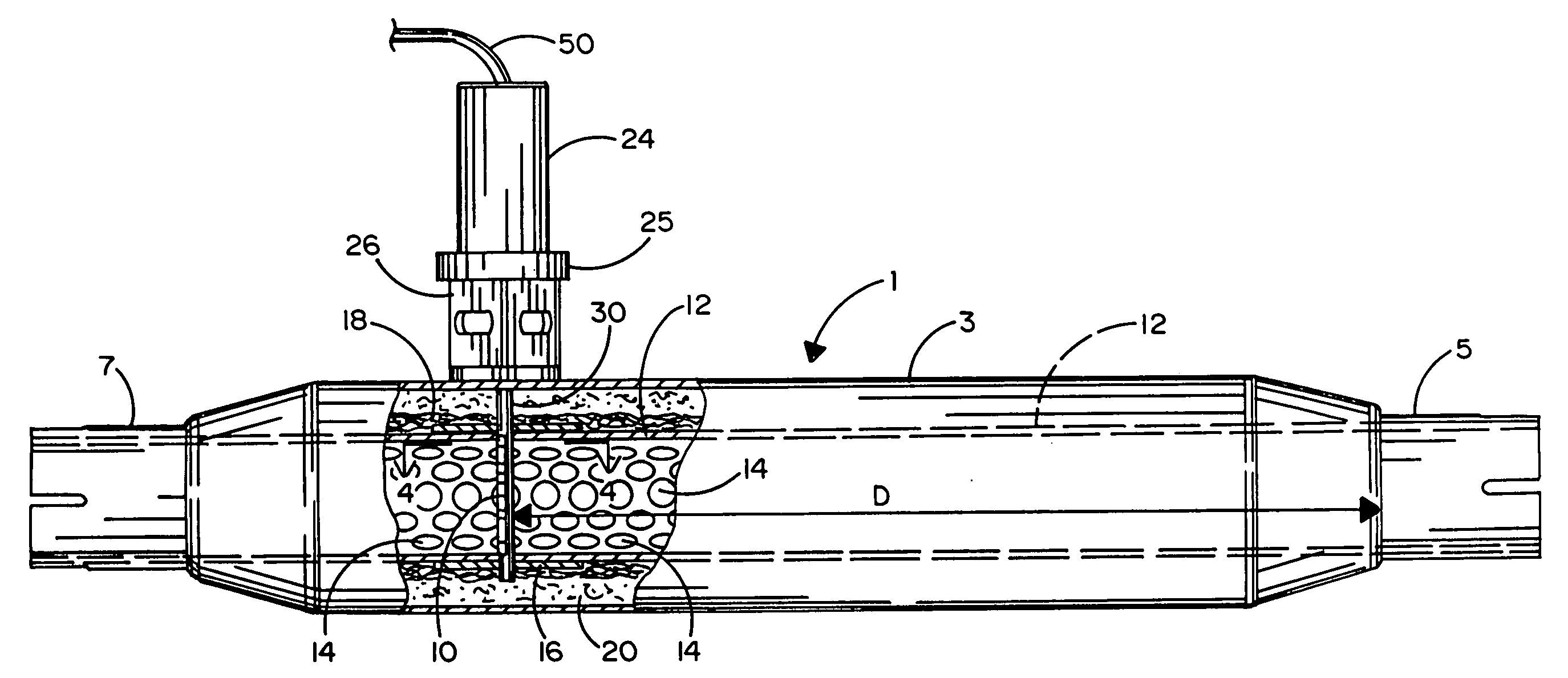
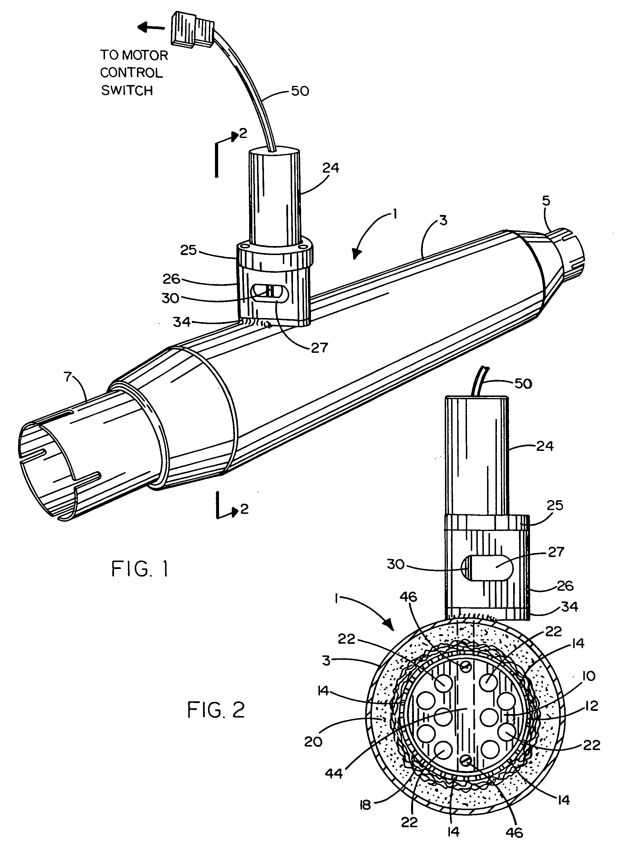
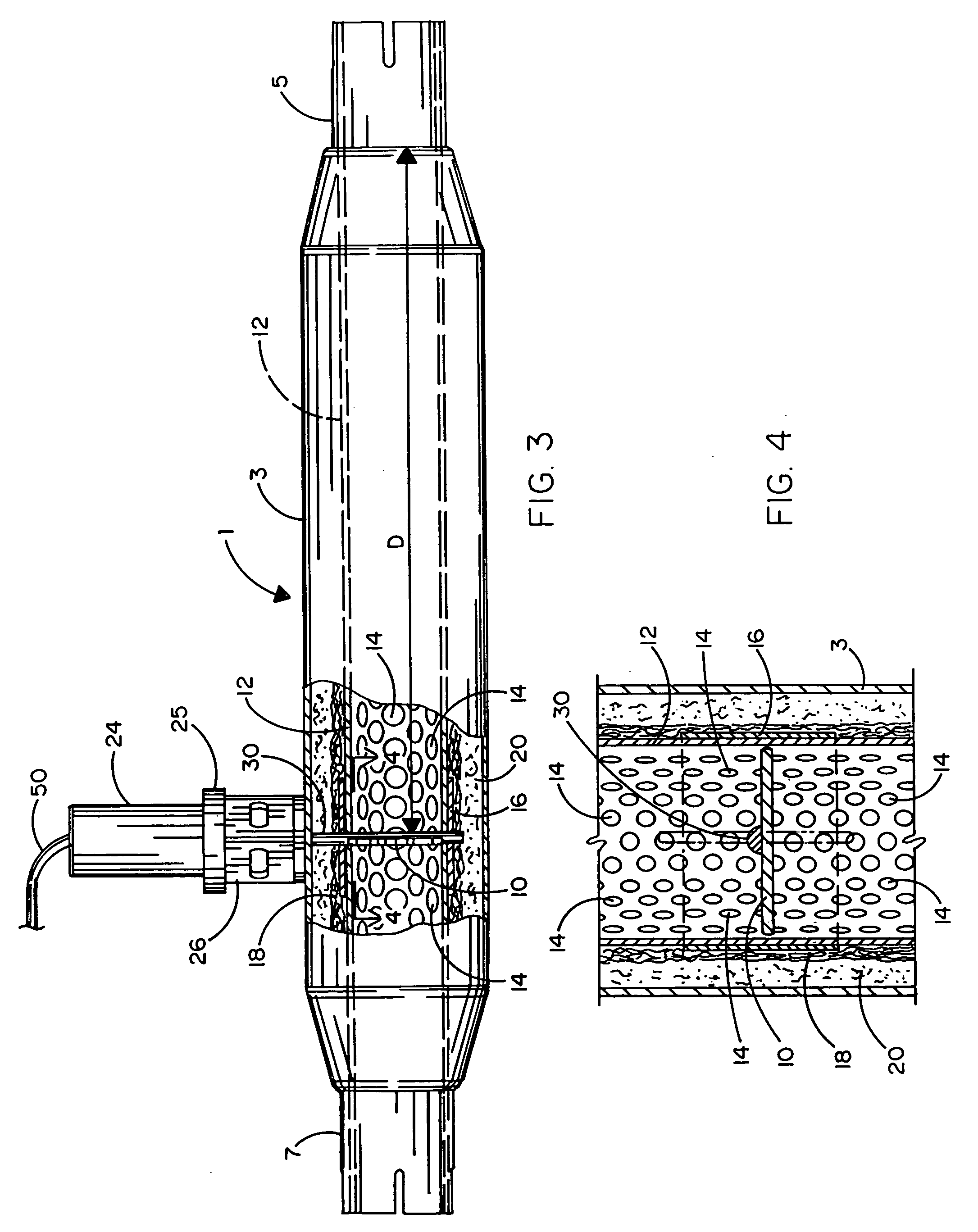
[0019]Referring concurrently to FIGS. 1-4 of the drawings, there is shown a muffler 1 having particular application as an after market product for installation on a motor vehicle, such as an automobile. However, it is within the scope of the present invention for the muffler 1 to be installed on other motor vehicles, such as motorcycles, trucks, boats, and the like. The muffler 1 includes a hollow, generally cylindrical outer body 3 having a typical length of approximately fourteen to twenty four inches. The muffler 1 includes an inlet end 5 to receive exhaust gases from the engine of the automobile. Located opposite the inlet end 5 of muffler 1 is an outlet end 7 through which the exhaust gases are distributed to the atmosphere. Mounting brackets (not shown) may be located around the outer muffler body 3 so that the muffler 1 can be easily installed on the automobile as a retrofit substitute for a stock muffler.

[0020]In accordance with the present improvement, a rotatable sound att...


PUM


Abstract

A muffler to be coupled to the engine of a motor vehicle (e.g., a car, truck, motor cycle, boat, and the like) so that exhaust gases emitted by the engine can be exhausted to the atmosphere. The muffler includes an outer cylindrical body and an inner cylindrical liner having a plurality of apertures formed therethrough. Sound absorbing packing material is located in an annular space between the outer body and the inner liner. An adjustable butterfly valve is located within the inner liner and rotatable between open and closed positions to control the gas flow through the liner, the sound generated by the muffler as a result thereof, and the performance of the engine to which the muffler is coupled. The rotation of the butterfly valve is controlled by an external DC motor or a continuous cable. The shaft of the motor or the cable is connected through the outer body and inner liner of the muffler to the butterfly valve. By closing a manually accessible motor control switch electrically connected to the motor or by pulling on the cable, the operator of the motor vehicle has the ability to control the rotation of the butterfly valve connected to the motor shaft or the cable while the vehicle is in motion.

Description

BACKGROUND OF THE INVENTION[0001]1. Field of the Invention[0002]This invention relates to an improved muffler for use with a motor vehicle, such as an automobile, truck, motorcycle, boat and the like. In particular, the improved muffler has an adjustable butterfly valve positioned therewithin so as to be rotatable between open and closed positions by the operator while the vehicle is in motion in order to selectively control the exhaust flow characteristics through the muffler, the corresponding sound generated by the muffler, and the performance of the engine to which the muffler is coupled.[0003]2. Background Art[0004]Virtually all engines that are manufactured today are coupled to a muffler so as to reduce the generation of sound as engine gases are exhausted to the atmosphere. For many motor vehicles, it is often possible to substitute a new muffler for the original stock muffler. Such a substitute muffler, which may be sold by the original manufacturer or as an after market pro...

Claims


Application Information

Patent Timeline
IPC IPC(8): F01N1/16
CPCF01N1/165
Inventor PACINI, LARRY W.PACINI, DONALD L.
Owner PACINI LARRY W
Why Eureka
Try Eureka