Milling tool as well as a milling insert

a technology of inserts and milling tools, which is applied in the field of milling tools, can solve the problems of poor working environment in the plant, difficult to master the formation of the tool, and high noise of the milling operation,

Active Publication Date: 2014-01-30
SANDVIK INTELLECTUAL PROPERTY AB
View PDF6 Cites 9 Cited by
  • Summary
  • Abstract
  • Description
  • Claims
  • Application Information

AI Technical Summary

Problems solved by technology

Disadvantages of previously known double-sided milling inserts having a round basic shape are, therefore, among other things that the chip formation may become difficult to master and that the milling operations produce rough and high sounds; this is something that creates a poor working environment in the plant in question.
A further shortcoming of previously known milling tools having round, double-sided milling

Method used


Image

  • Milling tool as well as a milling insert
  • Milling tool as well as a milling insert
  • Milling tool as well as a milling insert

Examples


Embodiment Construction

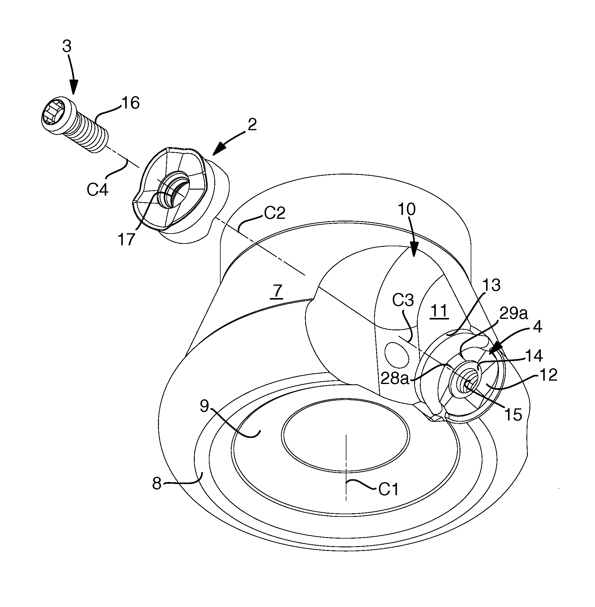
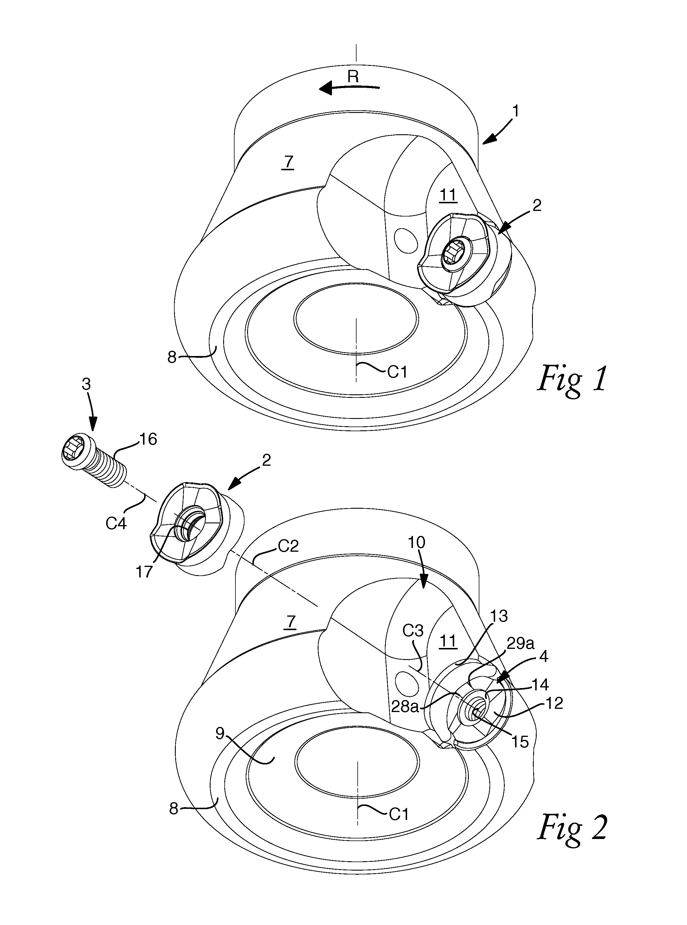
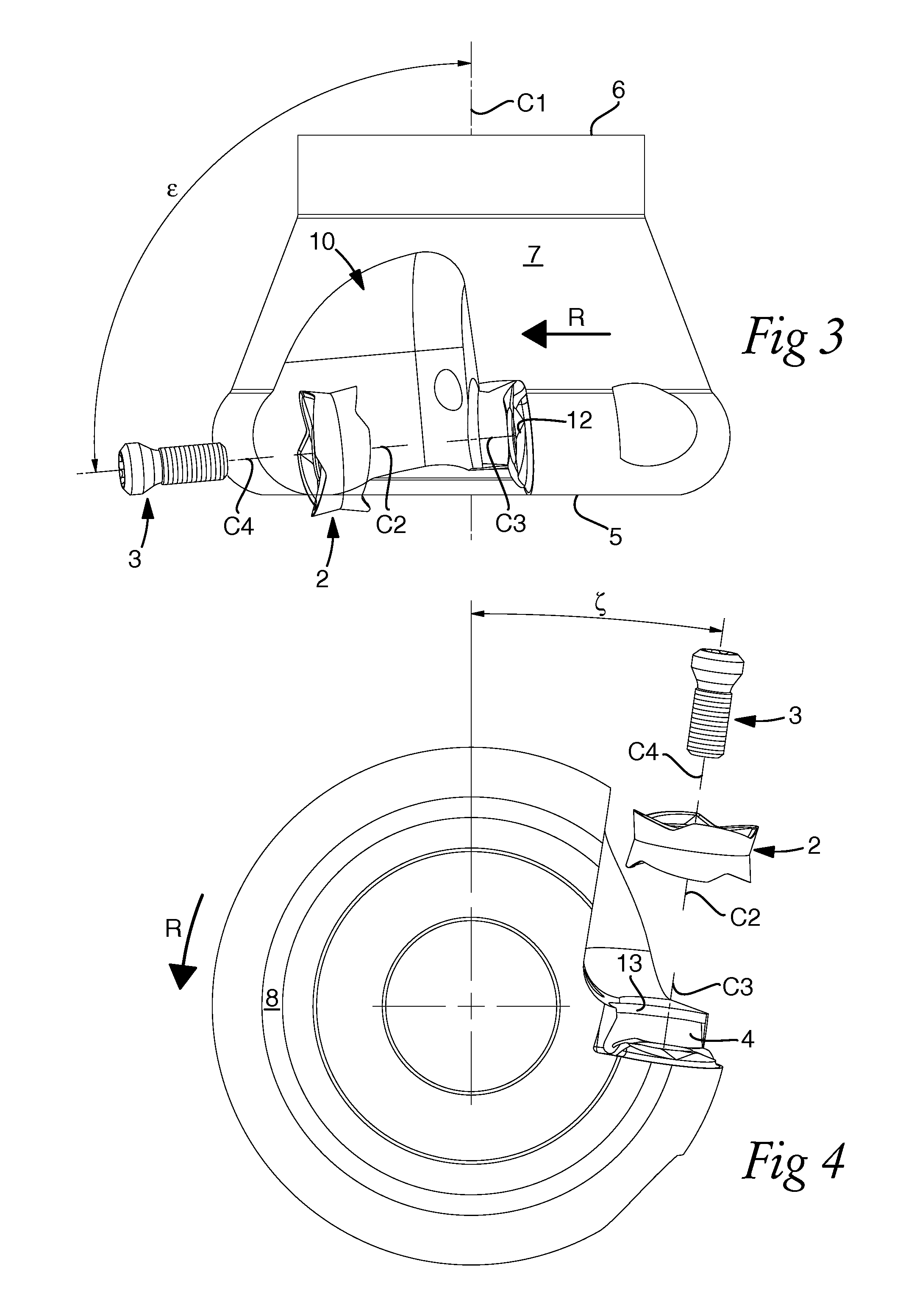
[0036]In FIGS. 1-4, there is illustrated a milling tool having a double-sided, indexable milling insert formed in accordance with the invention with a round basic shape. The tool includes a basic body 1 in the form of a so-called milling cutter head as well as a milling insert 2. In the tool, a tightening device 3 in the form of a screw is also included, which has the purpose of clamping the milling insert in a seat 4 in the basic body 1. In practice, the basic body 1 may be manufactured from steel and the milling insert 2 from a harder material, in particular cemented carbide. Also the screw 3 may be manufactured from steel, suitably a steel having a certain inherent elasticity.

[0037]The basic body 1 includes front and rear ends 5, 6 (see FIG. 3), between which there extends a centre axis C1 on which the same is rotatable, more precisely in the direction of the arrow R. In other words, the axis C1 is the rotation axis of the tool. A partly conical envelope surface 7 having a rotati...


PUM

PropertyMeasurementUnit
Fractionaaaaaaaaaa
Fractionaaaaaaaaaa
Lengthaaaaaaaaaa

Abstract

A double-sided, indexable milling insert has a round basic shape defined by an imaginary cylinder, which is concentric with a center axis and extends between two reference planes that extend perpendicular to the center axis and are equidistantly separated from a neutral plane. The milling insert includes a pair of opposite chip faces located in the reference planes between which an envelope surface concentric with the center axis extends, a plurality of identical and alternately usable cutting edges along the peripheries of the chip faces, and lock means for rotationally securing the milling insert in one of several predetermined index positions. The individual cutting edge has the shape of a wave trough and includes two edge segments that meet at a bottom point.

Description

TECHNICAL FIELD OF THE INVENTION[0001]In a first aspect, this invention relates to a milling tool of the type that comprises, on one hand, a basic body that includes front and rear ends, between which there extends a centre axis on which the basic body is rotatable and with which a rotationally symmetrical envelope surface is concentric, as well as a seat situated in a transition between the envelope surface and the front end, and on the other hand a double-sided, indexable milling insert, which has a round basic shape defined by an imaginary cylinder that is concentric with a centre axis and extends between two reference planes that extend perpendicular to the centre axis, and which comprises a pair of opposite chip faces, which are located in said reference planes and between which a circumferential envelope surface concentric with the centre axis of the milling insert extends, as well as a plurality of identical and alternately usable cutting edges along the periphery of the indi...

Claims


Application Information

Patent Timeline
IPC IPC(8): B23C5/22B23C5/20
CPCB23C5/205B23C5/2247B23C2200/283B23C5/06B23C2200/045B23C2200/206B23C2200/164B23C2200/168B23C2210/168Y10T407/192Y10T407/20Y10T407/23B23C5/2213B23C5/2304B23C2200/281B23C5/20
Inventor LEHTO, RALFVIKLUND, PER
Owner SANDVIK INTELLECTUAL PROPERTY AB
Why Eureka
Try Eureka