
Hinge device of a nacelle cowling of an aircraft engine on a supporting structure

Active Publication Date: 2008-01-31
AIRBUS OPERATIONS SAS
View PDF5 Cites 7 Cited by
  • Summary
  • Abstract
  • Description
  • Claims
  • Application Information

AI Technical Summary

Benefits of technology

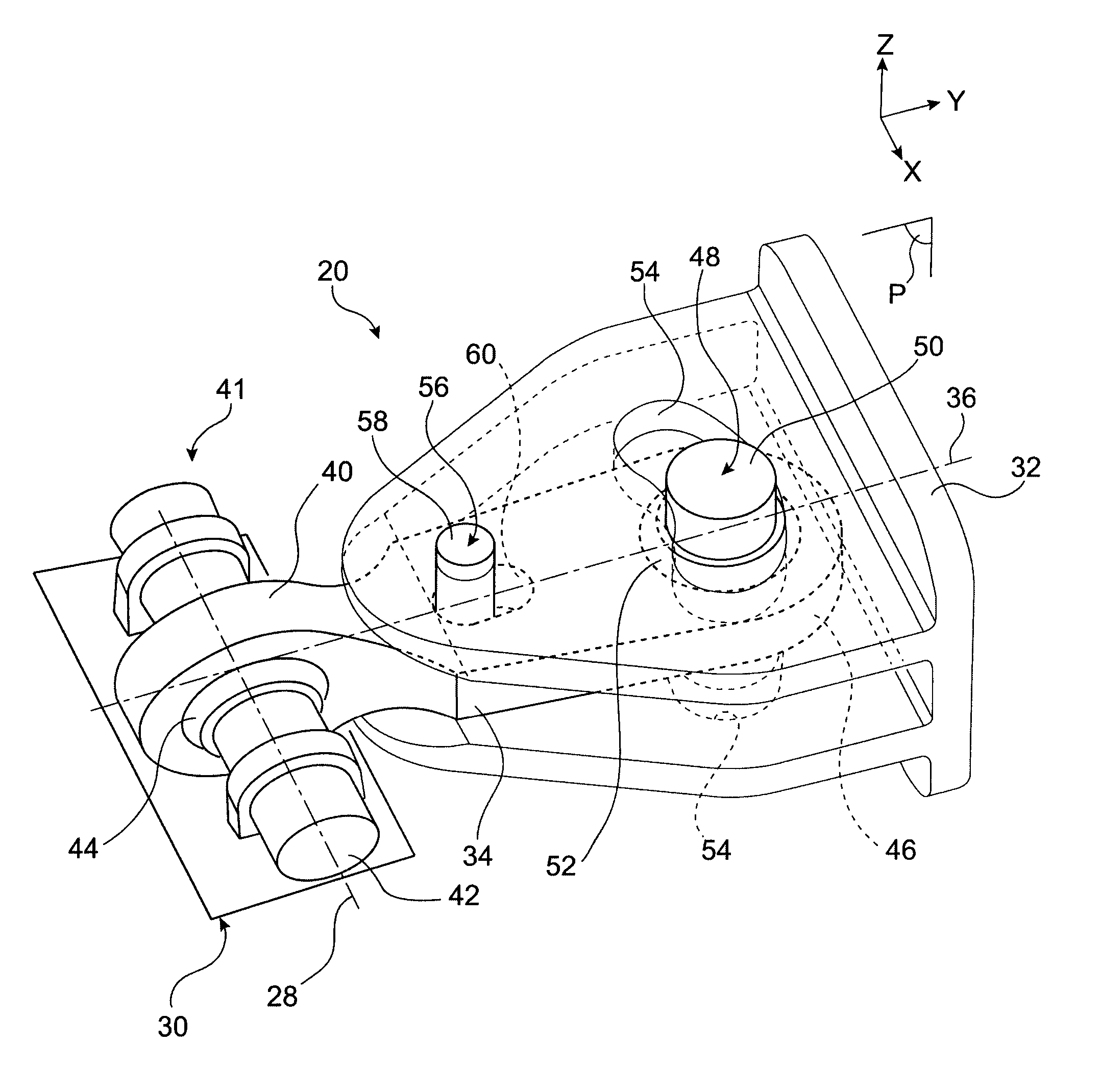
[0012] Consequently, during flight, when relative movements appear between the rigid engine mounting structure and a given nacelle cowling resulting primarily from the thermal dilation of the thrust take-up rods and occurring substantially according to the hinge axis of this same cowling, the link rod of the device then undergoes a movement with respect to the second fitting, which can be broken down into a rotation according to the pivot pin, and an additional relative movement such as a translation according to the longitudinal link rod direction, as mentioned above. This additional relative movement advantageously makes it possible to strongly limit and even completely prevent the approach of the cowling of the supporting structure at the location of said hinge device, since it allows the positioning of the first link rod end to be maintained on or in the vicinity of the hinge axis on which it is initially centred in non-biased mode, i.e. on the ground and cool.
[0015] The hole is preferably formed in the link rod, and the pivot pin is borne by the second fitting, although the reverse configuration is possible without going beyond the scope of the invention. In this preferred case, the hole can extend parallel to the longitudinal link rod direction, and the pivot pin can be orthogonal to this longitudinal link rod direction and to the hinge axis of the nacelle cowling. Of course, providing the hole parallel to the longitudinal link rod direction makes it possible to obtain the additional relative movement of the link rod with respect to the second fitting in the form of a translation in this same link rod direction, when the hinge device is seen according to the direction of the pivot pin.
[0016] Still preferably, the guide ramp is formed in the second fitting, and the guide pin is borne by the link rod, although the reverse configuration is possible without going beyond the scope of the invention. In this preferred case, the guide pin is borne by the link rod with the assistance of a swivel, which makes it possible in particular for the hinge device to have a so-called “semi-floating” character, i.e. providing a degree of freedom of movement in the vertical plane, facilitating the alignment of the assembly pin in the hinge axis of the nacelle cowling concerned.

Problems solved by technology

The disadvantage of this lies in the appearance of significant local mechanical stresses between the two elements supporting this same third “semi-floating” hinge device.

Method used


Image

  • Hinge device of a nacelle cowling of an aircraft engine on a supporting structure
  • Hinge device of a nacelle cowling of an aircraft engine on a supporting structure
  • Hinge device of a nacelle cowling of an aircraft engine on a supporting structure

Examples


Embodiment Construction

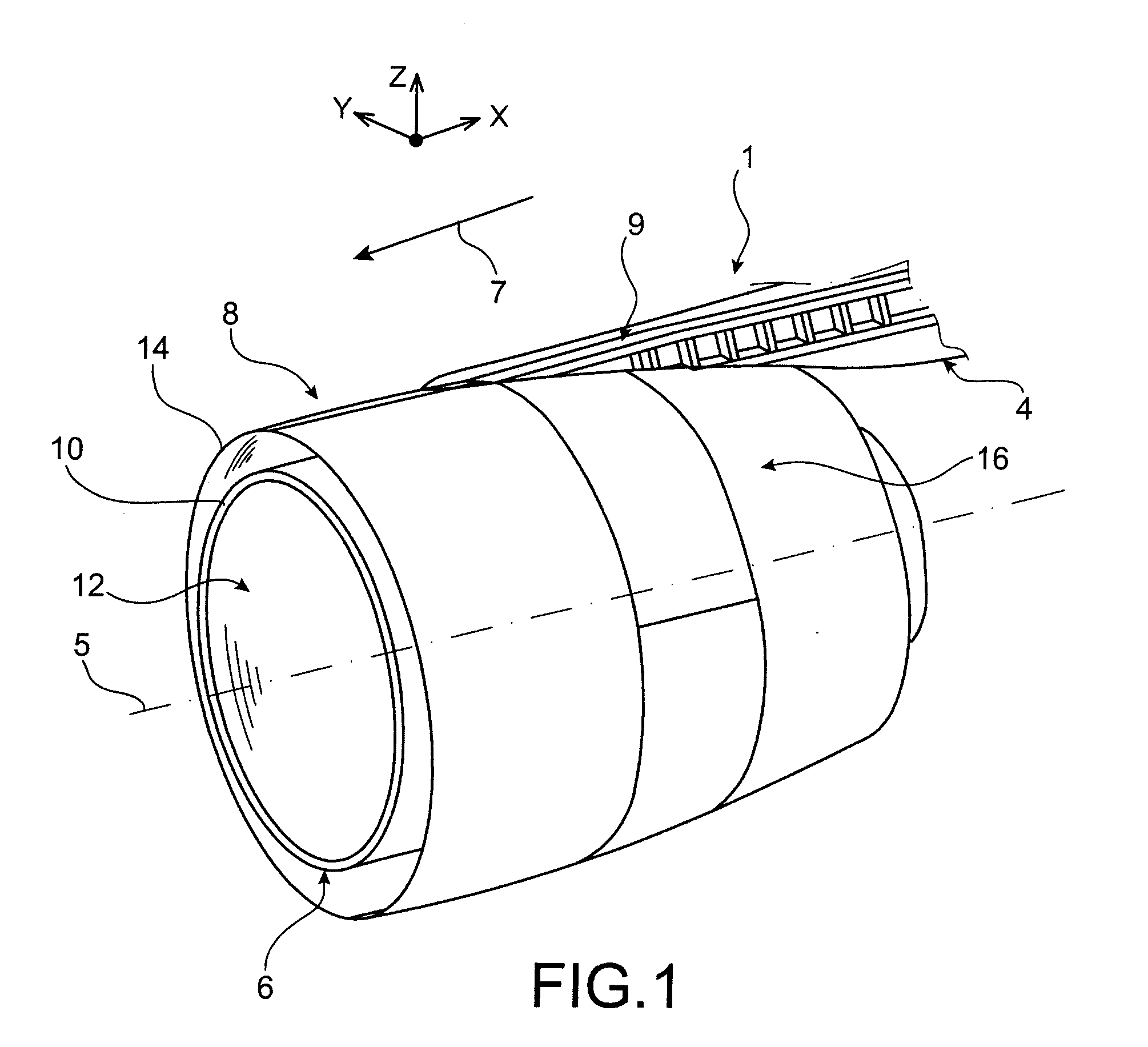
[0032]FIG. 1 shows an engine assembly 1 for an aircraft according to this invention, intended to be attached under a wing (not shown) of said aircraft, which assembly 1 comprises a mounting device or an engine mounting structure 4, an engine 6 such as a turbojet mounted under said device 4, as well as a nacelle 8 arranged around the engine.

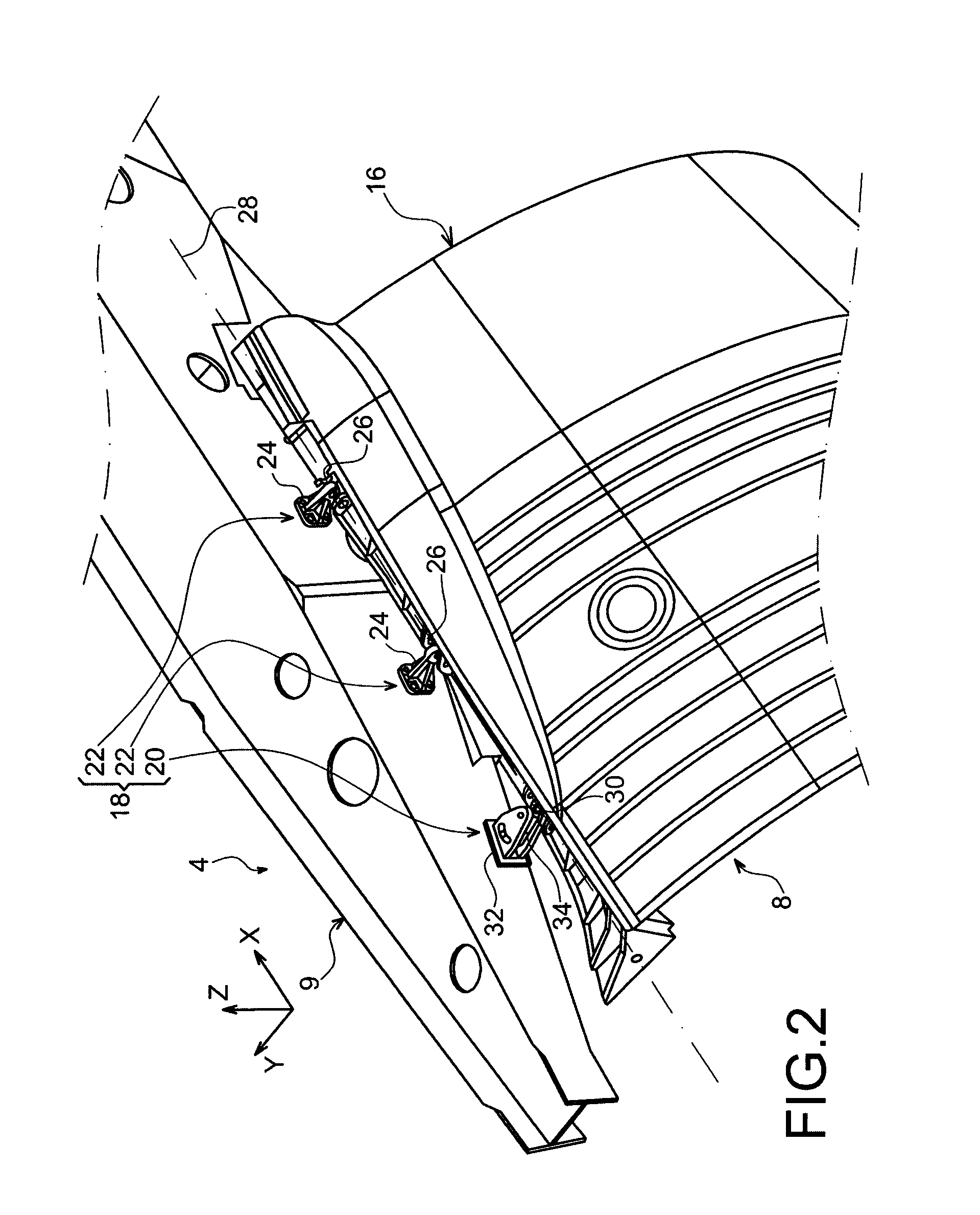
[0033] Generally, the mounting device 4 comprises a rigid structure 9 with mounting means (not shown) for mounting the engine 6, as well as another series of fasteners (not shown) for suspending said assembly 1 under the wings of the aircraft.

[0034] Throughout the following description, by convention, X will refer to the longitudinal direction of the assembly 1, which is also comparable to the longitudinal direction of the turbojet 6 and to that of the mounting device 4, with this direction X being parallel to a longitudinal axis 5 of said turbojet 6. In addition, Y will refer to the transverse direction with respect to the engine assembly 1 and...


PUM


Abstract

This invention relates to a hinge device (20) of a nacelle cowling of an aircraft engine (6) on a supporting structure, including two fittings as well as a link rod (34) connected thereto and mounted on the fitting (32) by means of an end connection (48). According to the invention, the link rod is also mounted on the fitting (32) by means of an intermediate connection (56) including a pivot pin (58) slidably housed in a hole (60), and the connection (48) includes a guide pin (50) slidably housed in a guide ramp (54), and the connections (48, 56) are designed so as to create, upon rotation of the link rod about the pin (58), a relative movement of the axis (50) in the ramp (54), simultaneously causing a relative movement of the pin (58) in the hole (54).

Description

TECHNICAL FIELD [0001] This invention relates in general to a hinge device of a nacelle cowling of an aircraft engine on a supporting structure, such as a mounting device, also called an engine mounting structure or EMS, normally used to suspend an engine below the wings of the aircraft, to mount said engine above these same wings, or to attach said engine to the rear portion of the aircraft fuselage. [0002] The invention can be used on any type of aircraft equipped with turbojets or turboprop engines. PRIOR ART [0003] Typically, to mount a nacelle cowling on a rigid / primary structure of an engine mounting structure, a hinge system is used, which includes a plurality of hinge devices, for example three, among which there are two conventional hinge devices and a third so-called “semi-floating” hinge device providing a degree of freedom of movement in the vertical plane. More specifically, the conventional hinge devices include two fittings respectively secured to the cowling and the ...

Claims


Application Information

Patent Timeline
IPC IPC(8): B64C1/14B64D27/00E05D7/00
CPCB64D29/06Y10T16/522E05Y2900/502E05D3/022F16C11/045
Inventor BEAUFORT, JACQUES
Owner AIRBUS OPERATIONS SAS
Learn More