Active rudder pedal mechanism with foreign object strike tolerance and articulating brake

a technology of foreign object strike tolerance and rudder pedal mechanism, which is applied in the direction of personal actuation, control initiation means, and joint controls, etc., can solve the problems of inadvertent movement of rudder pedals and/or rudder pedal mechanisms, suffer certain drawbacks, and present devices may not be useful in current fly-by-wire flight control systems

Inactive Publication Date: 2008-01-31
HONEYWELL INT INC
View PDF27 Cites 11 Cited by
  • Summary
  • Abstract
  • Description
  • Claims
  • Application Information

AI Technical Summary

Benefits of technology

[0009]The present invention provides a rudder pedal mechanism that is configured to exhibit foreign object strike tolerance and / or that allows for appropriate rudder control via the pedals without influencing brake operation, and vice-versa.

Problems solved by technology

For example, although highly unlikely, it is postulated that a bird (or other foreign object) could strike and penetrate the nose of the aircraft, and cause an inadvertent movement of the rudder pedals and / or rudder pedal mechanisms.
However, if the mechanical mechanisms are struck by an object and experience a compressive force, the links give way and do not, therefore, transmit a command to the rudder.
Although the present devices and methods for rudder pedals and associated mechanical mechanisms are generally safe, reliable, and robust, they do suffer certain drawbacks.
For example, present devices may not be useful in current fly-by-wire flight control systems.
Moreover, present mechanisms are configured such that brake operation may be undesirably influenced during rudder pedal operation.

Method used


Image

  • Active rudder pedal mechanism with foreign object strike tolerance and articulating brake
  • Active rudder pedal mechanism with foreign object strike tolerance and articulating brake
  • Active rudder pedal mechanism with foreign object strike tolerance and articulating brake

Examples


Embodiment Construction

[0017]The following detailed description is merely exemplary in nature and is not intended to limit the invention or the application and uses of the invention. Furthermore, there is no intention to be bound by any theory presented in the preceding background or the following detailed description.

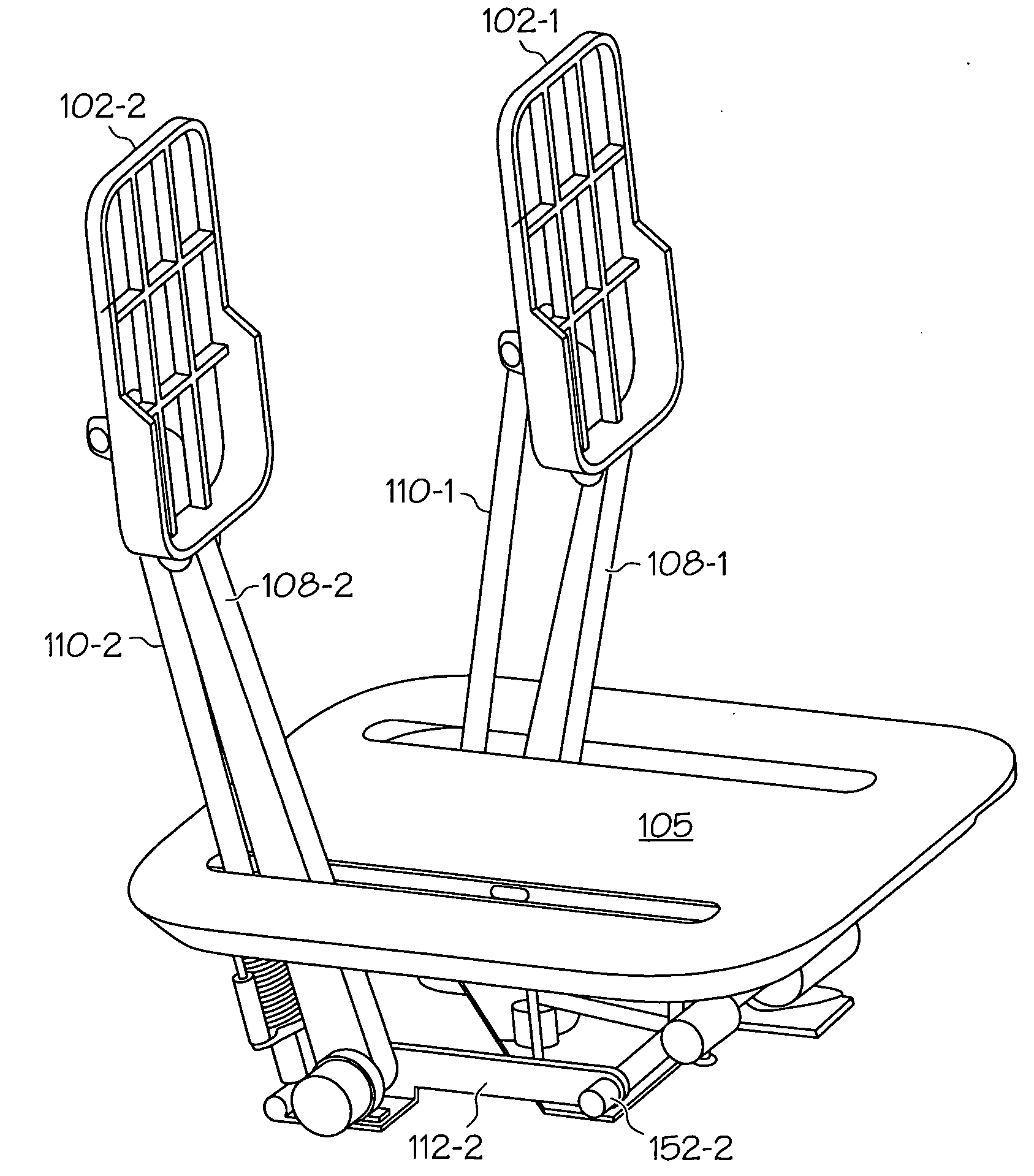
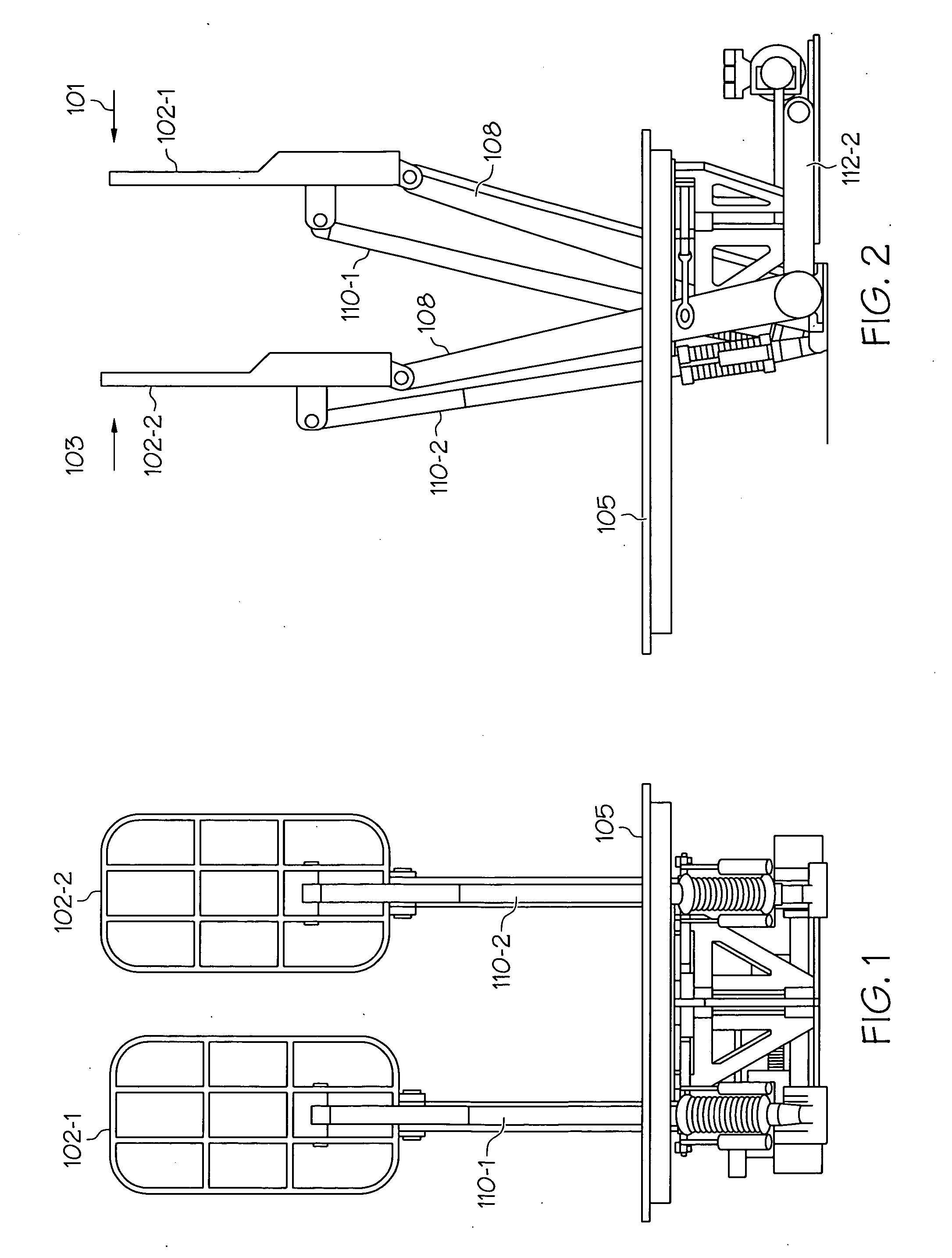
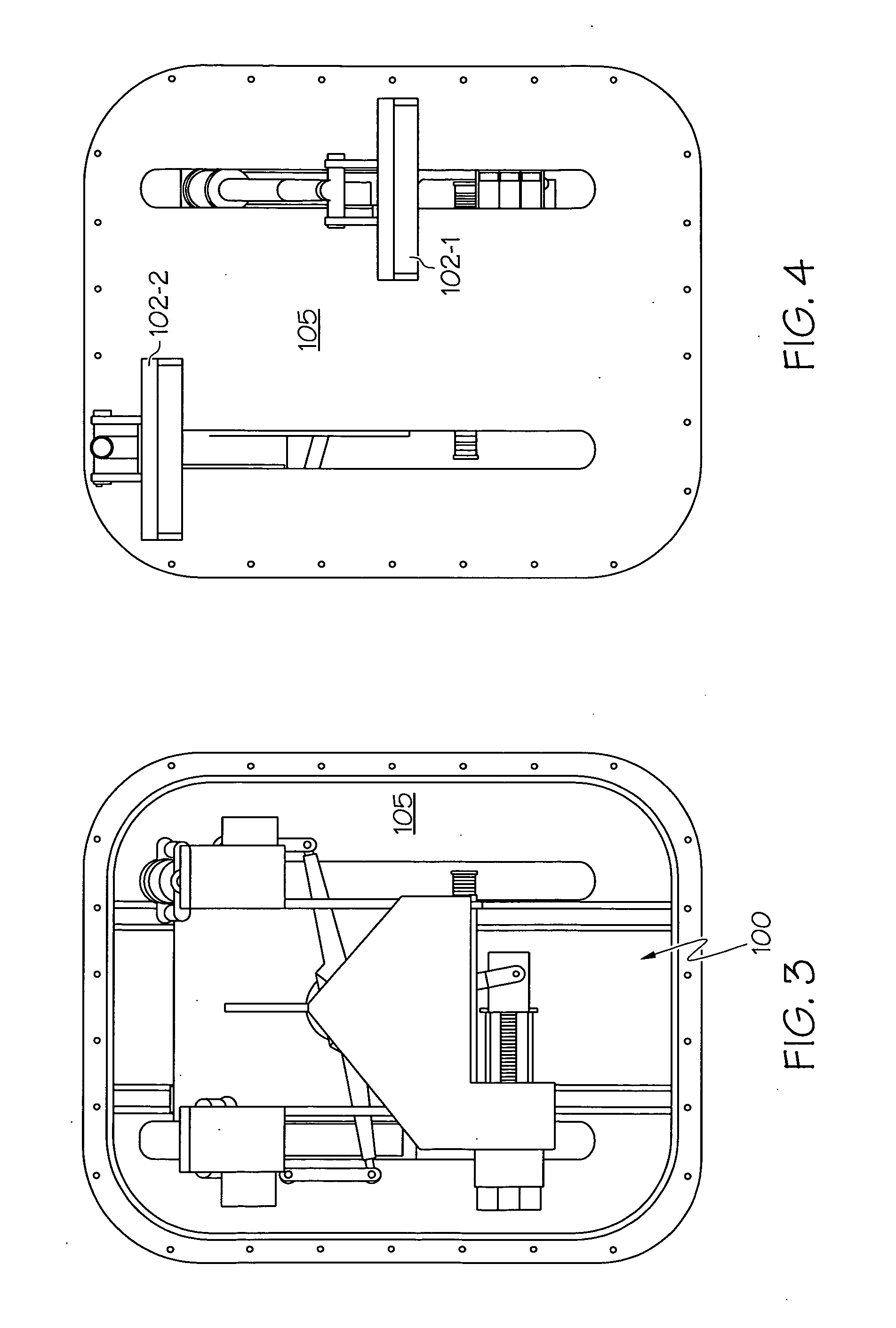
[0018]FIGS. 1-14 are various views of an exemplary embodiment of an active rudder pedal system 100. The system includes a pair of rudder pedals 102 (102-1, 102-2), a force transfer mechanism 104, and a rudder position command unit 106. The rudder pedals 102 are each configured to extend through a cockpit floor board 105, and to receive an input force from, for example, a pilot's foot and, in response to the received force, to move. The rudder pedals 102 are each coupled to the force transfer mechanism 104, which is in turn coupled to the rudder position command unit 106. In the depicted embodiment, the rudder pedals 102 are coupled to the force transfer mechanism 104 via a pair of pedal arms...


PUM


Abstract

A rudder pedal mechanism is configured with foreign object strike tolerance and/or with an articulating brake. The foreign object strike tolerance is implemented via a force transfer mechanism that is responsive to an input force supplied to the rudder pedal. The force transfer mechanism is configured to supply a transfer force to a rudder position command unit when the input force is supplied in a first direction, and to not supply the transfer force to the rudder position command unit when the input force is supplied in the second direction and exceeds at least a predetermined force magnitude. The articulating brake is implemented via a brake rod assembly that is rotationally coupled to the rudder pedal, and includes a first rod that is rotationally coupled to the rudder pedal, and a second rod that surrounds at least a portion of the first rod.

Description

CROSS-REFERENCE TO RELATED APPLICATIONS[0001]This application claims the benefit of U.S. Provisional Application No. 60 / 818,187, filed Jun. 30, 2006, and U.S. Provisional Application No. 60 / 818,188, also filed Jun. 30, 2006.TECHNICAL FIELD[0002]The present invention relates to a rudder pedal mechanism and, more particularly, to an active rudder pedal mechanism with foreign object strike tolerance and an improved brake mechanism.BACKGROUND[0003]Aircraft typically include a plurality of flight control surfaces that, when controllably positioned, guide the movement of the aircraft from one destination to another. The number and type of flight control surfaces included in an aircraft may vary, but typically include both primary flight control surfaces and secondary flight control surfaces. The primary flight control surfaces are those that are used to control aircraft movement in the pitch, yaw, and roll axes, and the secondary flight control surfaces are those that are used to influenc...

Claims


Application Information

Patent Timeline
Patent Type & Authority Applications(United States)
IPC IPC(8): B64C19/02
CPCB64C13/04B64C13/044
Inventor CHRISTENSEN, DONALD J.HANLON, CASEY
Owner HONEYWELL INT INC
Why Eureka
Try Eureka