Radiation attenuation corridor

a radiation attenuation and corridor technology, applied in the field of radiation shielding, can solve the problems of inability to damage healthy tissue, complicated use, and high cost of manufacturing methods, and achieve the effect of indirect path

Active Publication Date: 2008-01-31
TRINITY HEALTH CORP
View PDF5 Cites 8 Cited by
  • Summary
  • Abstract
  • Description
  • Claims
  • Application Information

AI Technical Summary

Benefits of technology

[0010] The placement of the angles in the radiation corridor increases the distance radiation must travel, and makes the path more indirect. This increases the contact the radiation emissions with the radiation shielding. In other words, the ionizing radiation bounces between wall sections until it is absorbed before reaching the outer door openings. Coupling this novel geometry with the placement of BPE attenuates the radiation to a point where a door is not necessary for blockage of radiation.

Problems solved by technology

While ionizing radiation is capable of destroying cancerous tissue, it is also capable of damaging healthy tissue inadvertently exposed thereto.
However, most of these methods are expensive to manufacture and can be complicated to use.
This is both time consuming and dangerous, as technicians and patients alike can get caught in the door if they are not careful.
Furthermore, it is time consuming for a therapist whenever the patient requires adjustment or assistance.
Moreover, the closing of a thick lead door has a negative psychological impact on the patient who can feel entombed in the therapy room.
Additionally, such a room is expensive and the required footprint is very large, resulting in a lot of unusable space.
Finally, it has been known for these heavy doors to become stuck in the closed position due to motor or hinge failure.

Method used


Image

  • Radiation attenuation corridor
  • Radiation attenuation corridor
  • Radiation attenuation corridor

Examples


Embodiment Construction

[0014] Referring now to the drawings, preferred embodiments of the present invention are shown in detail. Although the drawings represent embodiments of the present invention, the drawings are not necessarily to scale and certain features may be exaggerated to better illustrate and explain the present invention. The embodiments set forth herein are not intended to be exhaustive or to otherwise limit the invention to the precise forms disclosed in the following detailed description.

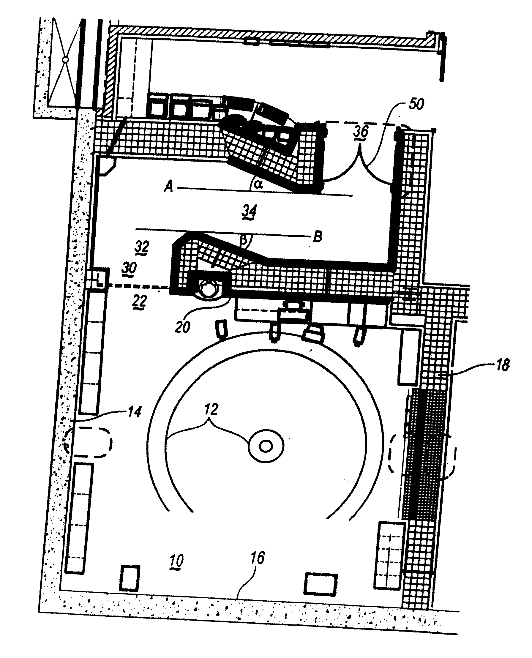
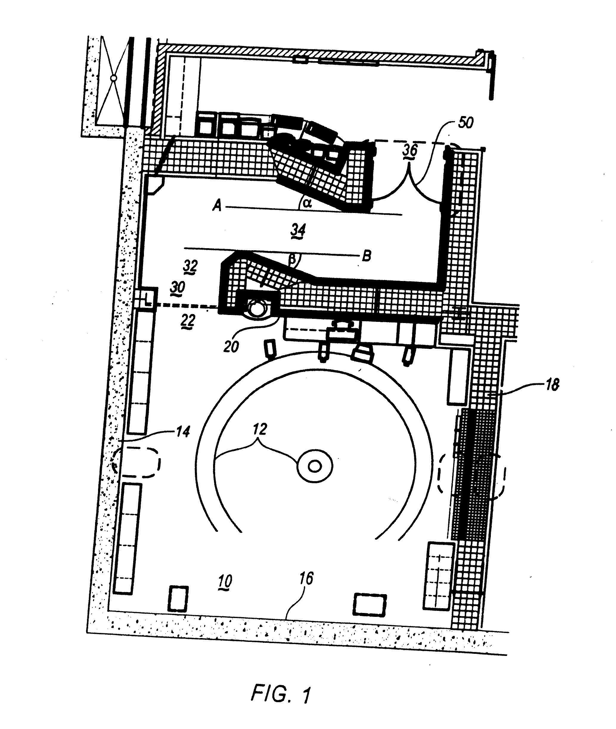
[0015] Referring now to FIG. 1 and 2, therapy room 10 includes a radiation source 12, a first wall 14, a second wall 16 a third wall 18 and a fourth wall 20. Fourth wall 20 includes an opening 22 leading to an access corridor 30, which extends along the first wall 14 away from the therapy room 10.

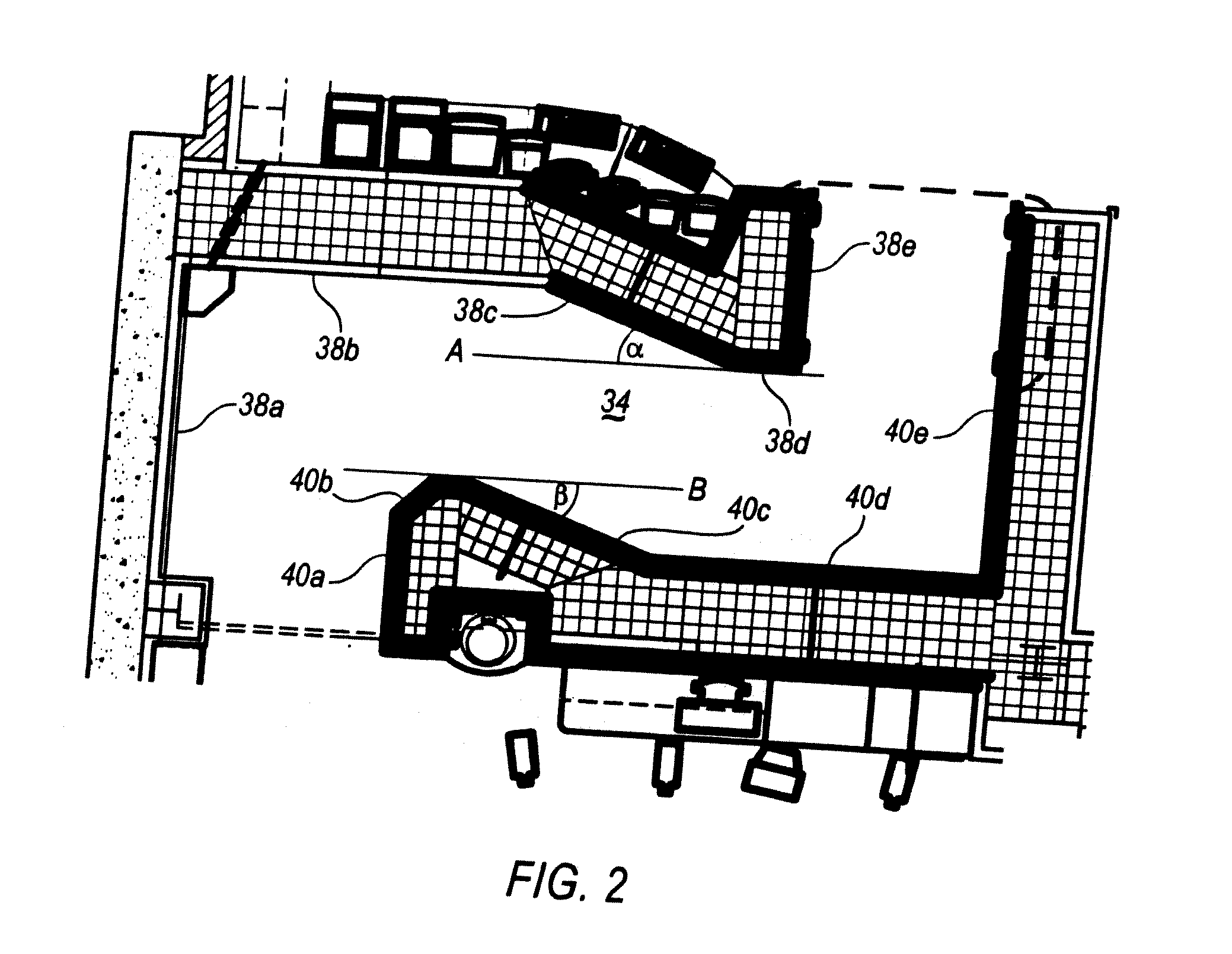
[0016] Access corridor 30 comprises a therapy room access portion 32, an angular traverse portion 34, and a control room access portion 36, and is defined throughout by a first corridor wall 38a -38e, a second c...


PUM


Abstract

A radiation attenuation corridor couples a radiation therapy room and a control room. The radiation attenuation corridor is made of a material that substantially absorbs ionizing radiation and substantially blocks the transmission of the ionizing radiation. Specific wall portions at the entrance of the corridor are covered with borated polyethylene (BPE). Specific wall portions diverge from an axis defined by the corridor by from about 10 degrees to about 45 degrees. The corridor thus leads out of the room and angles laterally across the wall of the therapy room, before angling again and opening to a safe room. The added angles in the radiation corridor increase the distance of radiation travel, and make the path more indirect, thereby increasing the contact of the radiation emissions with the radiation shielding and further attenuating the radiation.

Description

CROSS REFERENCE TO RELATED APPLICATION [0001] This application is a continuation of and claims priority to U.S. application Ser. No. 11 / 183,508 filed on Jul. 18, 2005 entitled “Radiation Attenuation Corridor”.TECHNICAL FIELD [0002] The present invention relates generally to radiation shielding and particularly to an improved radiation attenuation corridor for radiation treatment facilities. BACKGROUND OF THE INVENTION [0003] Radiation therapy utilizes several types of ionizing radiation, such as beta-rays, gamma rays and x-rays, as well as high-energy protons and neutrons applied to malignant tissue to prevent and control the spread of cancer. While ionizing radiation is capable of destroying cancerous tissue, it is also capable of damaging healthy tissue inadvertently exposed thereto. Thus, a necessary precondition for treatment is the safeguard of patients and personnel from accidental radiation exposure. [0004] Various methods of shielding radiation in rooms and walls are known a...

Claims


Application Information

Patent Timeline
Patent Type & Authority Applications(United States)
IPC IPC(8): G21F7/00
CPCA61N2005/1094G21F7/00G21Y2004/30G21Y2002/301G21Y2002/501G21Y2002/201
Inventor BICHAY, TEWFIK J.
Owner TRINITY HEALTH CORP
Why Eureka
Try Eureka