Extended E Matrix Integrated Magnetics (MIM) Core

a magnetic core and matrix integrated technology, applied in the direction of transformer/inductance magnetic core, magnets, magnet bodies, etc., can solve the problems of insufficient two-phase interleaving to meet the switching ripple specifications of inductor current and output voltage, increase volume and weight, and sluggish transient response in response to dynamic load conditions, etc., to achieve the effect of easy and less expensive fabrication

Inactive Publication Date: 2008-01-31
MYPAQ HLDG LTD
View PDF56 Cites 134 Cited by
  • Summary
  • Abstract
  • Description
  • Claims
  • Application Information

AI Technical Summary

Benefits of technology

[0008] The present invention discloses a matrix integrated magnetics (MIM) core structure that provides a single, low profile core solution for both isolated and non-isolated converter topologies, is easier and less expensive to fabricate, is scalable to an arbitrary number of interleaving phases and provides a minimal length for an additional inductor winding around the center leg.

Problems solved by technology

For applications where higher currents (>50 A) are required at low (<3.3 V) to moderate (˜12V) voltages at high efficiency and power density, two-phase interleaving might be inadequate to meet switching ripple specifications on the inductor currents and output voltage.
A larger output capacitor can reduce output voltage ripple but will increase the volume and weight of the converter and result in sluggish transient response in response to dynamic load conditions.
However, utilizing multiple discrete E-cores to implement multiphase interleaving topologies increases component count and interconnect losses, resulting in poor power density and efficiency.
An additional limitation to using E-cores for high current applications is the detrimental effect of the fringing flux due to the limited cross sectional area of the gapped center leg.
This results in increased I2R losses in the windings and reduced efficiency.
To reduce eddy current induction due to fringing flux, the windings are placed a safe distance away from the air gap, resulting in poor utilization of the core window area.
In addition, the fringing flux represents a loss of inductance which results in increased switching ripple in the winding currents, leading to higher I2R losses and poor efficiency.

Method used


Image

  • Extended E Matrix Integrated Magnetics (MIM) Core
  • Extended E Matrix Integrated Magnetics (MIM) Core
  • Extended E Matrix Integrated Magnetics (MIM) Core

Examples


Embodiment Construction

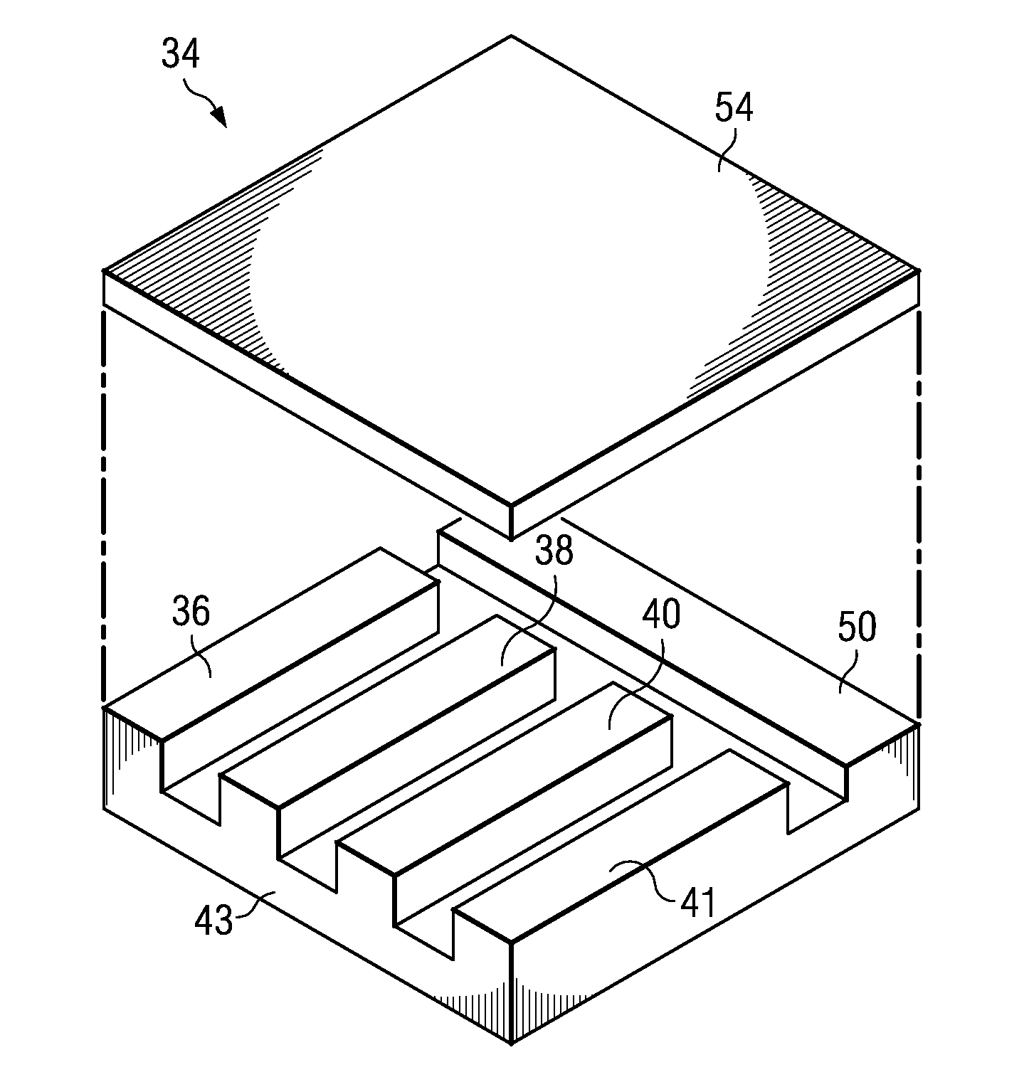
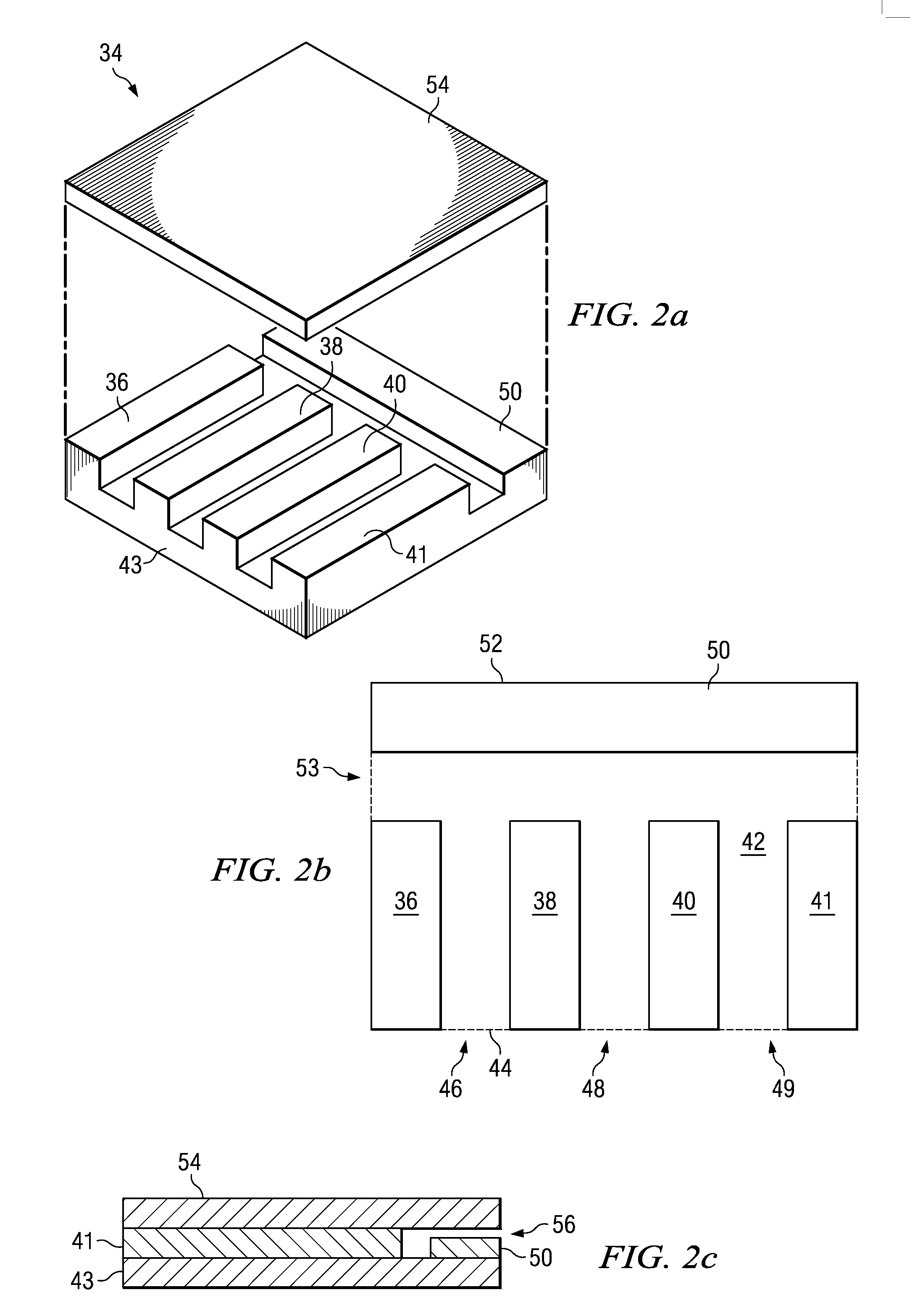
[0019] The present invention provides a matrix integrated magnetics (MIM) core structure, that provides a single, low profile core solution for both isolated and non-isolated converter topologies, is easier and less expensive to fabricate, is scalable to an arbitrary number of interleaving phases and provides a minimal length for an additional inductor winding around the center leg.

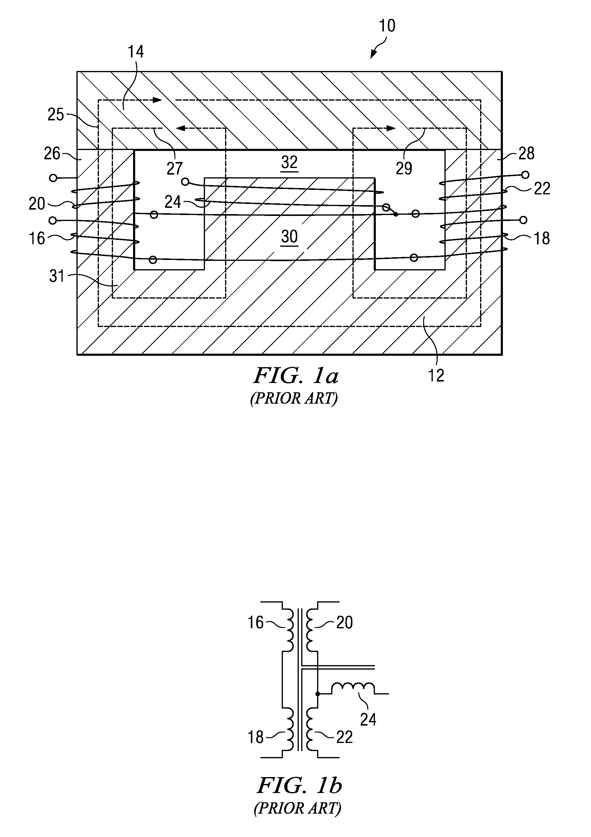
[0020] Copending U.S. patent applications Ser. No. 10 / 126,477 entitled “Core Structure” filed Apr. 18, 2002 (now U.S. Pat. No. 6,873,237, issued Mar. 29, 2005) and Ser. No. 10 / 302,095 entitled “Core Structure and Interleaved DC-DC Converter Topology” filed Nov. 21, 2002 (now U.S. Pat. No. 7,046,523, issued May 16, 2006) introduce MIM core structures in cross and radial configurations. The basic MIM core provides for low profile magnetics due to higher center leg cross sectional area and lower air gap height, better core utilization and uniform flux distribution, and improved efficiency and lower losses o...


PUM

PropertyMeasurementUnit
output voltageaaaaaaaaaa
inductor currentsaaaaaaaaaa

Abstract

A matrix integrated magnetics (MIM) “Extended E” core in which a plurality of outer legs are disposed on a base and separated along a first outer edge to define windows there between. A center leg is disposed on the top region of the base and separated from the outer legs to define a center window. The center leg is suitably positioned along a second outer edge opposite the first or between outer legs positioned along opposing outer edges. A plate is disposed on the outer legs opposite the base.

Description

CROSS-REFERENCE TO RELATED APPLICATIONS [0001] This application is a divisional of application Ser. No. 10 / 922,067, filed Aug. 19, 2004, which is a continuation-in-part of applications Ser. No. 10 / 126,477, filed Apr. 18, 2002 and Ser. No. 10 / 302,095, filed Nov. 21, 2002, all of which are hereby incorporated by reference.FIELD OF THE INVENTION [0002] This invention relates to the field of switched-mode power converters, and particularly to a matrix integrated magnetics (MIM) core structure. DESCRIPTION OF THE RELATED ART [0003] Switch-mode power converters are key components in many military and commercial systems for the conversion, control and conditioning of electrical power and often govern performance and size. Power density, efficiency and reliability are key metrics used to evaluate power converters. Transformers and inductors used within power converters constitute a significant percentage of their volume and weight, and hence determine power density, specific power, efficien...

Claims


Application Information

Patent Timeline
Patent Type & Authority Applications(United States)
IPC IPC(8): H01F27/24H01F41/02H01F3/08H01F17/04H01F30/06H02M7/04
CPCH01F27/24H01F27/255H01F30/06Y10T29/4902H02M7/043H01F3/08H01F17/04H01F2038/006
Inventor CHANDRASEKARAN, SRIRAMMEHROTRA, VIVEK
Owner MYPAQ HLDG LTD
Why Eureka
Try Eureka