Magnetic head for perpendicular magnetic recording and method of manufacturing same

a magnetic recording and perpendicular technology, applied in the direction of magnetic recording heads, data recording, instruments, etc., can solve the problems of inability to solve the foregoing problems, difficulty in defining the throat height with accuracy, and inability to define the structur

Active Publication Date: 2008-01-31
HEADWAY TECH INC +1
View PDF9 Cites 15 Cited by
  • Summary
  • Abstract
  • Description
  • Claims
  • Application Information

AI Technical Summary

Benefits of technology

[0023]It is an object of the invention to provide a magnetic head for perpendicular magnetic recording having a structure in which an end face of a pole layer and an end face of a shield are adjacent to each other with a gap layer disposed in between in a medium facing surface, the head being c

Problems solved by technology

In a magnetic disk drive of the perpendicular magnetic recording system that exhibits a better capability of writing on a recording medium than the longitudinal magnetic recording system, in particular, if the above-mentioned skew is created, problems arise, such as a phenomenon in which data stored on an adjacent track is erased when data is written on a specific track (that is hereinafter called adjacent track erasing) or unwanted writing is performed between a

Method used


Image

  • Magnetic head for perpendicular magnetic recording and method of manufacturing same
  • Magnetic head for perpendicular magnetic recording and method of manufacturing same
  • Magnetic head for perpendicular magnetic recording and method of manufacturing same

Examples


first embodiment

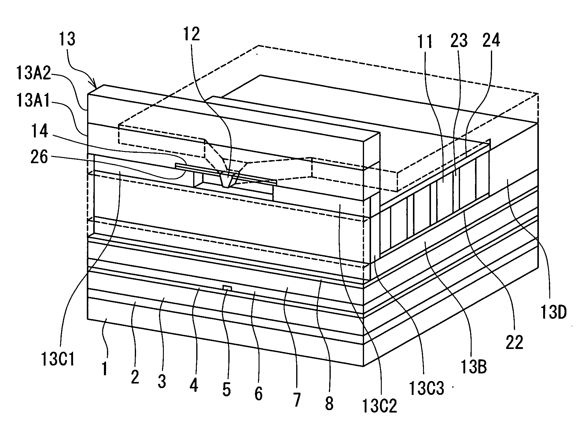
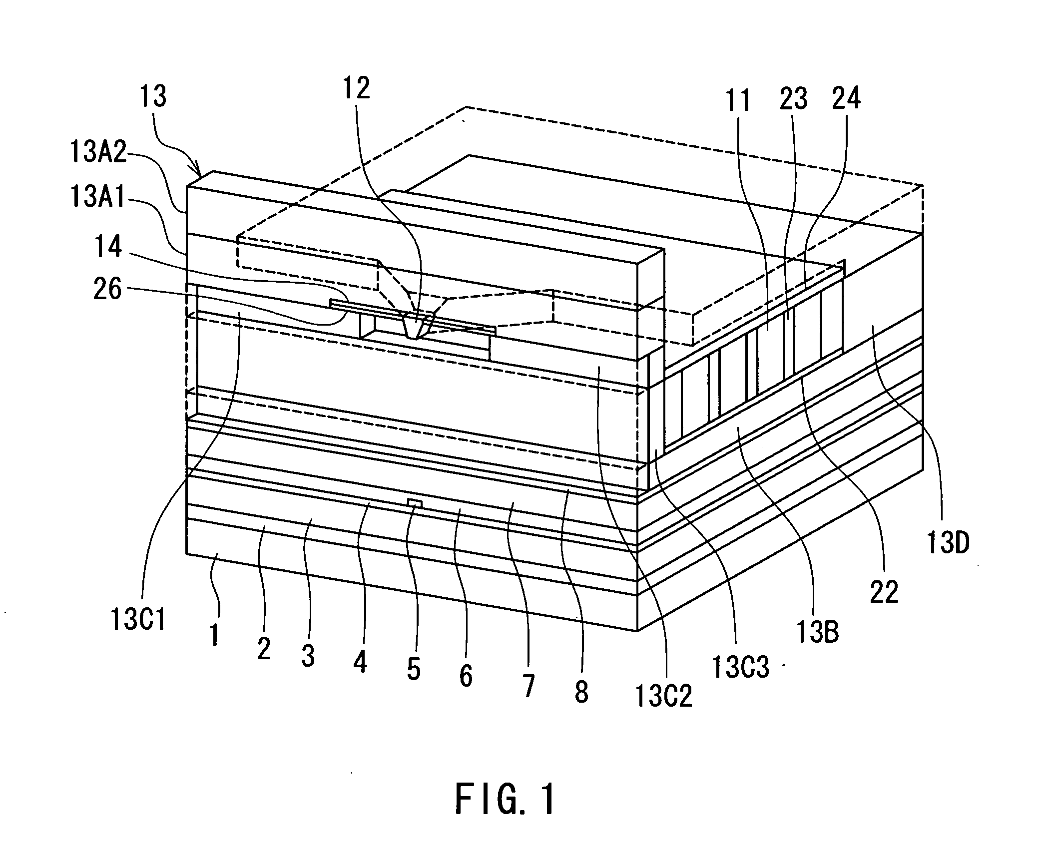
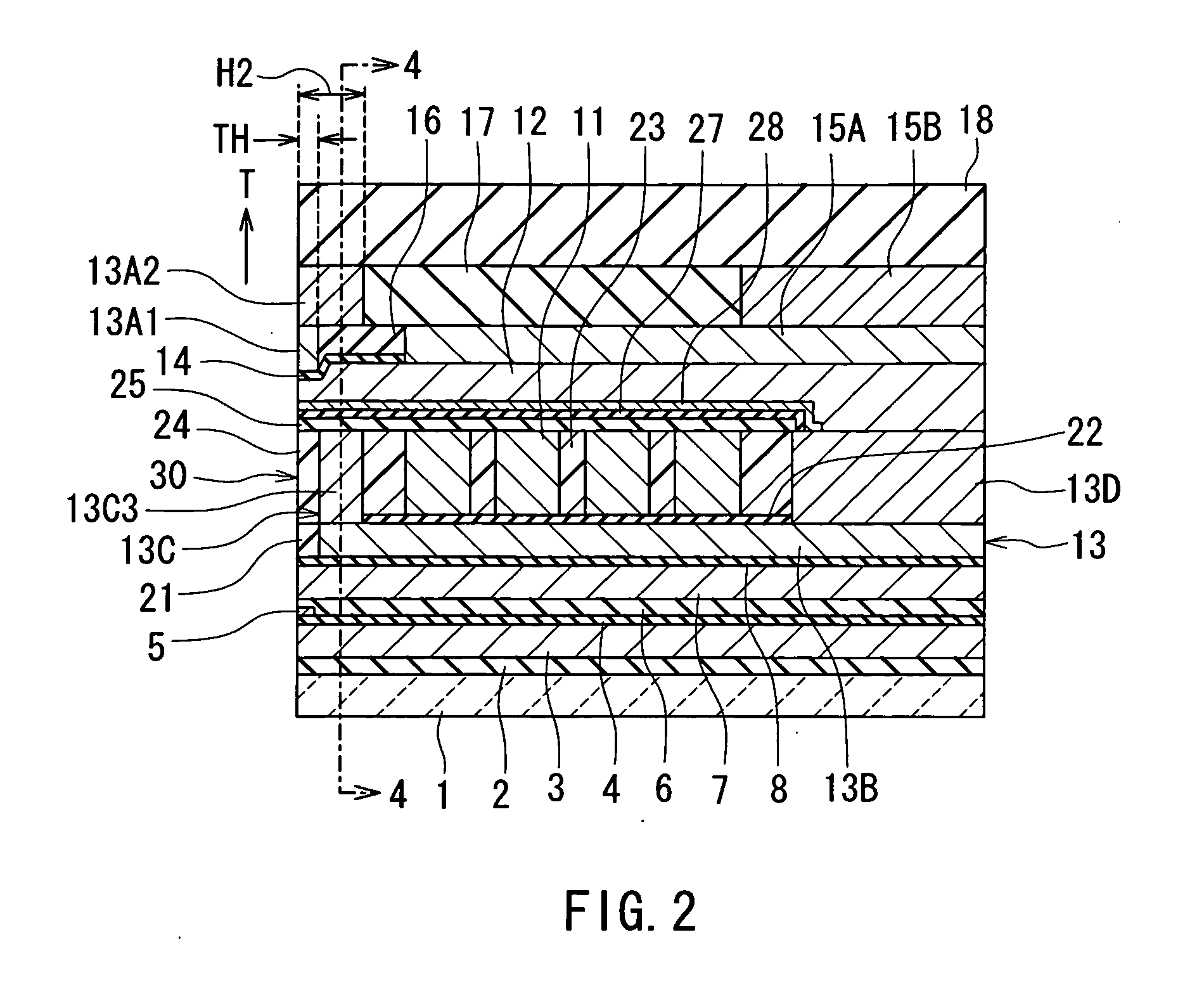
[0090]Preferred embodiments of the invention will now be described in detail with reference to the accompanying drawings. Reference is now made to FIG. 1 to FIG. 5 to describe the configuration of a magnetic head for perpendicular magnetic recording of a first embodiment of the invention. FIG. 1 is a perspective view illustrating a portion of the magnetic head of the first embodiment in a neighborhood of the medium facing surface. FIG. 2 is a cross-sectional view for illustrating the configuration of the magnetic head of the embodiment. FIG. 2 illustrates a cross section orthogonal to the medium facing surface and a surface of a substrate. The arrow indicated with T in FIG. 2 shows the direction of travel of a recording medium. FIG. 3 is a front view of the medium facing surface of the magnetic head of the embodiment. FIG. 4 is a cross-sectional view taken along line 4-4 of FIG. 2. FIG. 5 is a top view for illustrating a pole layer and a shield of the magnetic head of the embodiment...

modification examples

[0167]First and second modification examples of the embodiment will now be described. Reference is now made to FIG. 18 and FIG. 19 to describe a magnetic head of the first modification example. FIG. 18 is a cross-sectional view illustrating the configuration of the magnetic head of the first modification example. FIG. 18 illustrates a cross section orthogonal to the medium facing surface and the surface of the substrate. The arrow indicated with T in FIG. 18 shows the direction of travel of the recording medium. FIG. 19 is a front view illustrating the pole layer and the shield of the magnetic head of the first modification example.

[0168]In the first modification example, the shape of the second layer 13A2 of the shield 13 is similar to that of the first layer 13A1. That is, as shown in FIG. 19, the shape of the second layer 13A2 is one having a middle portion and two side portions which is the same as the shape of the first layer 13A1. Furthermore, in the first modification example...

second embodiment

[0172]Reference is now made to FIG. 21 to FIG. 23 to describe a magnetic head and a method of manufacturing the same of a second embodiment of the invention. FIG. 21 is a cross-sectional view of the magnetic head of the second embodiment. FIG. 21 illustrates a cross section orthogonal to the medium facing surface and the surface of the substrate. The arrow indicated with T in FIG. 21 shows the direction of travel of a recording medium. FIG. 22 is a front view illustrating the medium facing surface of the magnetic head for perpendicular magnetic recording of the second embodiment. FIG. 23 is a cross-sectional view taken along line 23-23 of FIG. 21.

[0173]In the magnetic head of the second embodiment, an insulating layer 47 is provided to cover the coil 11 and the insulating layer 23. The insulating layer 47 is made of alumina, for example.

[0174]In the second embodiment the second coupling portion 13D incorporates: a coupling layer 13D1 connected to the third layer 13B; and a lower yok...


PUM


Abstract

A shield incorporates: a first layer, a second layer, a third layer, a first coupling portion, and a second coupling portion. The first layer has: a first surface located in a region of a medium facing surface forward of an end face of a pole layer along the direction of travel of a recording medium; a second surface opposed to the pole layer; and a third surface opposite to the second surface. The second layer touches the third surface. The third layer is disposed in a region sandwiching the pole layer with the first layer. The first coupling portion couples the first layer to the third layer without touching the pole layer. The second coupling portion is located farther from the medium facing surface than the first coupling portion and couples the pole layer to the third layer.

Description

BACKGROUND OF THE INVENTION[0001]1. Field of the Invention[0002]The present invention relates to a magnetic head for perpendicular magnetic recording that is used for writing data on a recording medium by means of a perpendicular magnetic recording system and to a method of manufacturing such a magnetic head.[0003]2. Description of the Related Art[0004]The recording systems of magnetic read / write devices include a longitudinal magnetic recording system wherein signals are magnetized in the direction along the surface of the recording medium (the longitudinal direction) and a perpendicular magnetic recording system wherein signals are magnetized in the direction orthogonal to the surface of the recording medium. It is known that the perpendicular magnetic recording system is harder to be affected by thermal fluctuation of the recording medium and capable of implementing higher linear recording density, compared with the longitudinal magnetic recording system.[0005]Like magnetic heads...

Claims


Application Information

Patent Timeline
IPC IPC(8): G11B5/127
CPCG11B5/11G11B5/1278G11B5/315G11B5/3116G11B5/3146G11B5/1871
Inventor SASAKI, YOSHITAKAITOH, HIROYUKISHIMIZU, TATSUSHISHIMIZU, TATSUYA
Owner HEADWAY TECH INC
Why Eureka
Try Eureka