Magnetic head for perpendicular magnetic recording and method of manufacturing same

a magnetic recording and perpendicular technology, applied in the direction of magnetic recording heads, data recording, instruments, etc., can solve the problems of inability to solve the foregoing problems, difficulty in defining the throat height with accuracy, and inability to define the structur

Active Publication Date: 2009-10-27
HEADWAY TECH INC
View PDF23 Cites 9 Cited by
  • Summary
  • Abstract
  • Description
  • Claims
  • Application Information

AI Technical Summary

Benefits of technology

[0023]It is an object of the invention to provide a magnetic head for perpendicular magnetic recording having a structure in which an end face of a pole layer and an end face of a shield are adjacent to each other with a gap layer disposed in between in a medium facing surface, the head being capable of defining the throat height with accuracy, suppressing protrusion of an end portion of the shield closer to the medium facing surface due to the heat produced by the coil, and suppressing the wide-range adjacent track erase, and to provide a method of manufacturing such a magnetic head.
[0037]According to the magnetic head for perpendicular magnetic recording of the invention or the method of manufacturing the same, the first and second layers of the shield are disposed in the regions sandwiching the pole layer. As a result, according to the invention, it is possible to suppress the wide-range adjacent track erase. According to the invention, part of the coil passes through the space surrounded by the pole layer, the second layer, the first coupling portion and the second coupling portion. As a result, according to the invention, it is possible to suppress protrusion of the end portion of the first layer closer to the medium facing surface due to expansion of the insulating layer disposed around the coil. Consequently, the invention makes it possible to define the throat height with accuracy and to suppress protrusion of the end portion of the shield closer to the medium facing surface due to the heat produced by the coil.

Problems solved by technology

In a magnetic disk drive of the perpendicular magnetic recording system that exhibits a better capability of writing on a recording medium than the longitudinal magnetic recording system, in particular, if the above-mentioned skew is created, problems arise, such as a phenomenon in which data stored on an adjacent track is erased when data is written on a specific track (that is hereinafter called adjacent track erasing) or unwanted writing is performed between adjacent two tracks.
The first problem of the head of FIG. 43 is that it is difficult to define the throat height TH with accuracy.
However, the magnetic head having such a structure is not capable of solving the foregoing problems, that is, the first problem that it is difficult to define the throat height with accuracy and the second problem that the end portion of the shield layer closer to the medium facing surface protrudes due to the heat produced by the coil.

Method used


Image

  • Magnetic head for perpendicular magnetic recording and method of manufacturing same
  • Magnetic head for perpendicular magnetic recording and method of manufacturing same
  • Magnetic head for perpendicular magnetic recording and method of manufacturing same

Examples


first embodiment

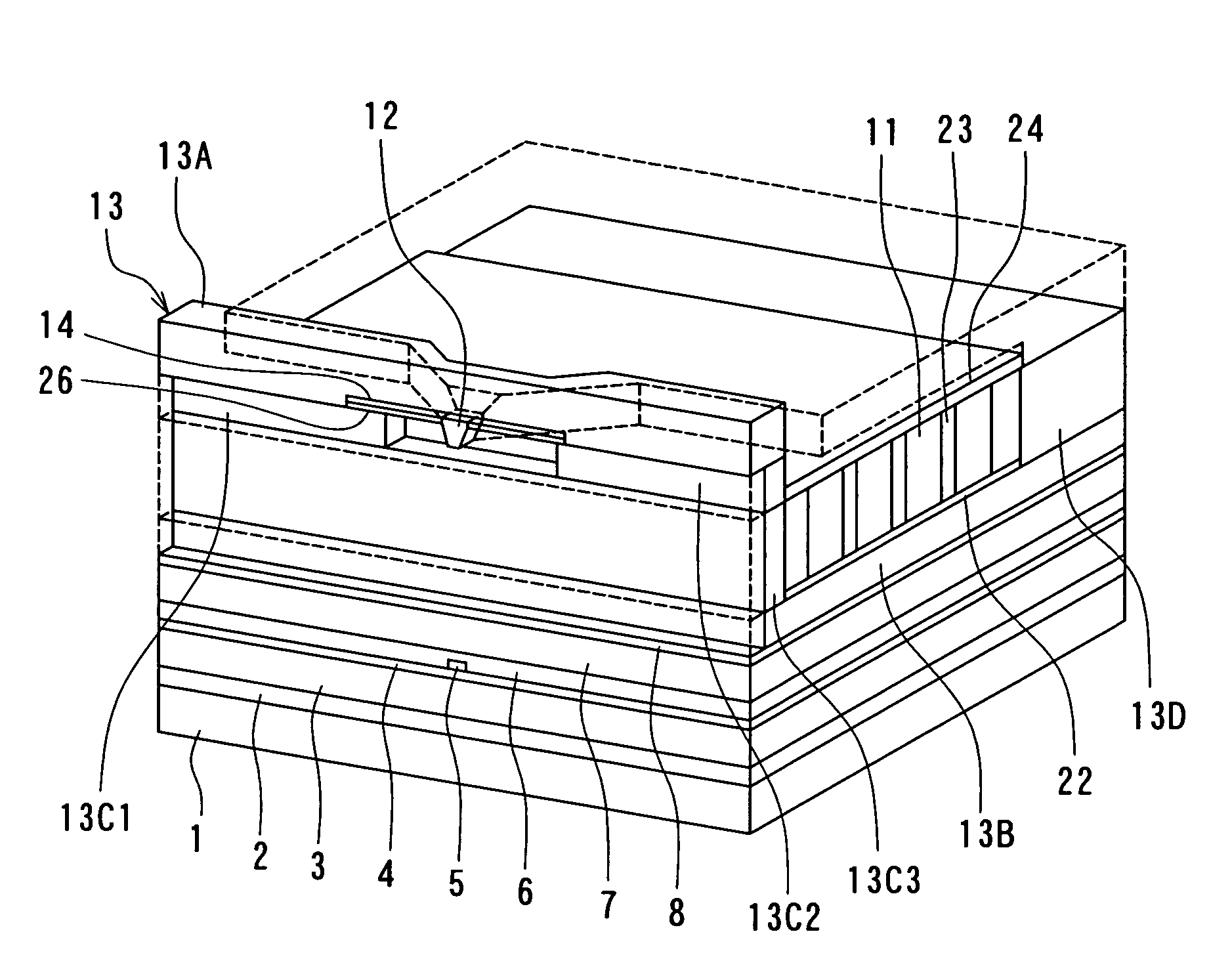
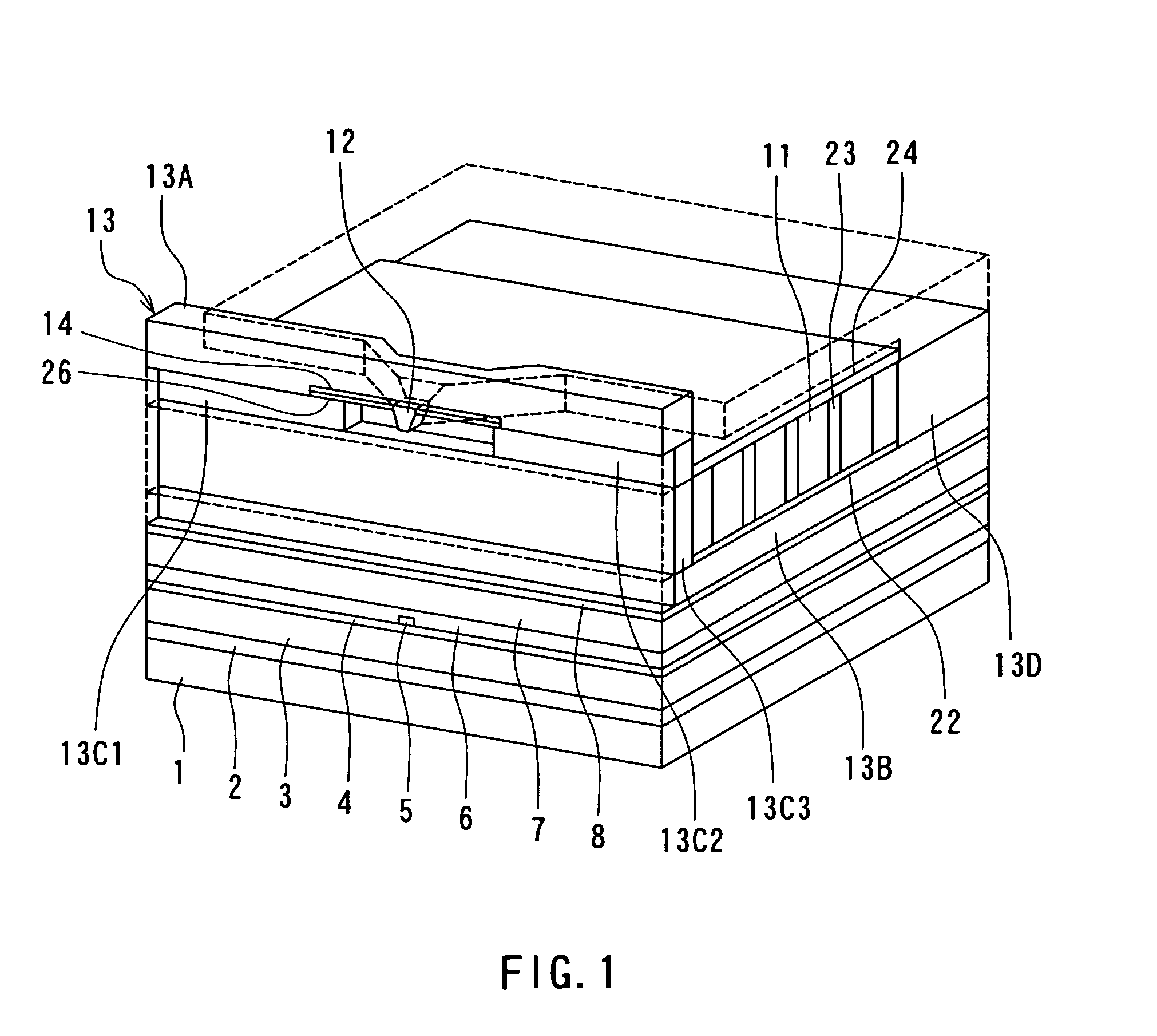
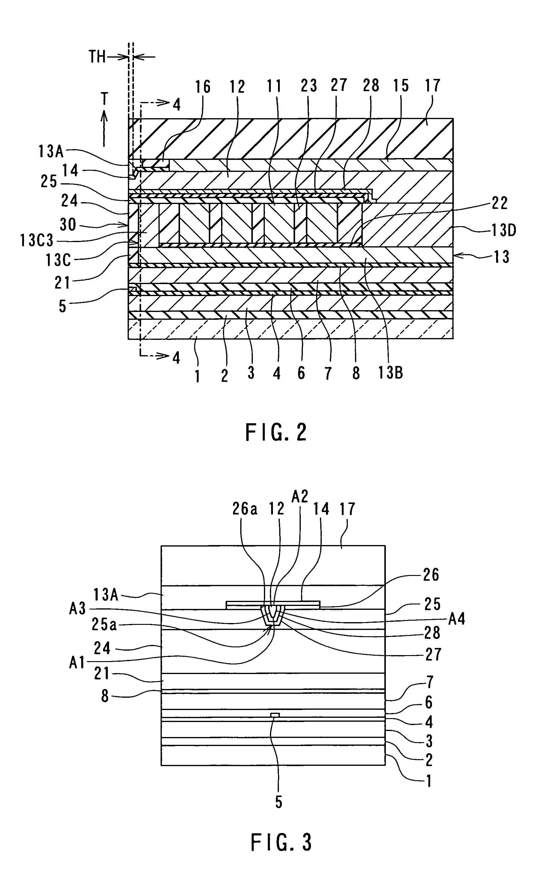
[0082]Preferred embodiments of the invention will now be described in detail with reference to the accompanying drawings. Reference is now made to FIG. 1 to FIG. 5 to describe the configuration of a magnetic head for perpendicular magnetic recording of a first embodiment of the invention. FIG. 1 is a perspective view illustrating a portion of the magnetic head of the first embodiment in a neighborhood of the medium facing surface. FIG. 2 is a cross-sectional view for illustrating the configuration of the magnetic head of the embodiment. FIG. 2 illustrates a cross section orthogonal to the medium facing surface and a surface of a substrate. The arrow indicated with T in FIG. 2 shows the direction of travel of a recording medium. FIG. 3 is a front view of the medium facing surface of the magnetic head of the embodiment. FIG. 4 is a cross-sectional view taken along line 4-4 of FIG. 2. FIG. 5 is a top view for illustrating a pole layer and a shield of the magnetic head of the embodiment...

modification examples

[0157]First and second modification examples of the embodiment will now be described. Reference is now made to FIG. 18 to FIG. 21 to describe a method of manufacturing a magnetic head of the first modification example. FIG. 18 to FIG. 21 each illustrate a cross section of a layered structure obtained in manufacturing process of the magnetic head orthogonal to the medium facing surface and the substrate. In FIG. 18 to FIG. 21 the portions closer to the substrate 1 than the top shield layer 7 are omitted.

[0158]FIG. 18 illustrates the step that follows the step shown in FIG. 13A to FIG. 13C. In the step, first, a nonmagnetic film 41 made of a nonmagnetic material such as alumina is formed by sputtering, for example, on the entire top surface of the layered structure. Next, a photoresist layer is formed on the entire top surface of the layered structure. The photoresist layer is then patterned to form a mask 42 for etching portions of the magnetic layer 12P and the nonmagnetic film 41. ...

second embodiment

[0164]A magnetic head and a method of manufacturing the same of a second embodiment of the invention will now be described. Reference is now made to FIG. 23 and FIG. 24 to describe the configuration of the magnetic head of the second embodiment. FIG. 23 is a front view of the medium facing surface of the magnetic head of the embodiment. FIG. 24 is a plan view illustrating the pole layer and the shield of the magnetic head of the embodiment.

[0165]As shown in FIG. 23 and FIG. 24, the shield 13 of the magnetic head of the second embodiment incorporates a first side shield layer 13E and a second side shield layer 13F in addition to the first layer 13A, the second layer 13B, the first coupling portion 13C and the second coupling portion 13D. The side shield layers 13E and 13F are connected to the first layer 13A and disposed on both sides of the pole layer 12 opposed to each other in the direction of track width. Each of the side shield layers 13E and 13F has an end face located in the m...


PUM

PropertyMeasurementUnit
thicknessaaaaaaaaaa
heightaaaaaaaaaa
thicknessaaaaaaaaaa

Abstract

A pole layer has an end face located in a medium facing surface, allows a magnetic flux corresponding to a magnetic field generated by a coil to pass therethrough, and generates a write magnetic field for writing data on a recording medium by using a perpendicular magnetic recording system. A shield incorporates: a first layer having an end face located in a region of the medium facing surface forward of the end face of the pole layer along the direction of travel of the recording medium; a second layer disposed in a region sandwiching the pole layer with the first layer; a first coupling portion coupling the first layer to the second layer without touching the pole layer; and a second coupling portion coupling the pole layer to the second layer and located farther from the medium facing surface than the first coupling portion.

Description

BACKGROUND OF THE INVENTION[0001]1. Field of the Invention[0002]The present invention relates to a magnetic head for perpendicular magnetic recording that is used for writing data on a recording medium by means of a perpendicular magnetic recording system and to a method of manufacturing such a magnetic head.[0003]2. Description of the Related Art[0004]The recording systems of magnetic read / write devices include a longitudinal magnetic recording system wherein signals are magnetized in the direction along the surface of the recording medium (the longitudinal direction) and a perpendicular magnetic recording system wherein signals are magnetized in the direction orthogonal to the surface of the recording medium. It is known that the perpendicular magnetic recording system is harder to be affected by thermal fluctuation of the recording medium and capable of implementing higher linear recording density, compared with the longitudinal magnetic recording system.[0005]Like magnetic heads...

Claims


Application Information

Patent Timeline
Patent Type & Authority Patents(United States)
IPC IPC(8): G11B5/127
CPCG11B5/1278G11B5/112G11B5/3163
Inventor SASAKI, YOSHITAKAITOH, HIROYUKILI, DONG-HONGSMYTH, JOSEPHGUAN, LIJIETANG, YAW-SHING
Owner HEADWAY TECH INC
Why Eureka
Try Eureka