Cover member of airbag device

a technology of airbags and cover parts, which is applied in the direction of identification means, vehicle components, instruments, etc., can solve the problems of deteriorating workability at the time of fitting, affecting and affecting the work efficiency of the door portion, so as to improve the workability of the lock receiving portion and improve the workability of the lock. , the effect of improving productivity and manufacturability

Inactive Publication Date: 2015-05-12
NIHON PLAST CO LTD
View PDF22 Cites 9 Cited by
  • Summary
  • Abstract
  • Description
  • Claims
  • Application Information

AI Technical Summary

Benefits of technology

[0009]The present invention has been made to solve the conventional problem described above, and it is an object of the present invention to provide a cover member of an airbag device, by which it is possible to improve productivity and manufacturability while allowing an ornamental member to be reliably fixed to a door portion.
[0027]According to the first aspect of the present invention, the first support portion, which is positioned on a predetermined straight line approximately perpendicular to a broken line of a hinge portion, and the second and third support portions, which are positioned in line symmetry with respect to the predetermined straight line, are set in the support portion that supports the mounting member with respect to the back face side of the door portion, so that it is possible to receive the centrifugal force, which is applied to the mounting member due to the expansion of the door portion, with good balance by the first to third support portions. Consequently, the ornamental member can be reliably fixed to the door portion with preventing the fixing pin from being excessively locked into the lock receiving portion more than necessary, so that it is possible to improve locking workability of the lock receiving portion and the fixing pin, resulting in the improvement of productivity and manufacturability.
[0028]According to the second aspect of the present invention, in addition to the effect of the cover member of the airbag device of the first aspect, at least one of the first to third support portions of the support portion protruding from the back face side of the door portion has a cylindrical shape having the recess therein, so that when the cover body is formed of synthetic resin, a sink mark is difficult to occur in the surface side of the door portion of the cover body, resulting in the further improvement of an external appearance.
[0029]According to the third aspect of the present invention, in addition to the effect of the cover member of an airbag device of the first aspect or the second aspect, the periphery of the mounting member is surrounded by the protrusion protruding from the back face side of the door portion, so that the mounting member can be held at the fixed position of the door portion more reliably with respect to the centrifugal force applied when the door portion is expanded.
[0030]According to the fourth aspect of the present invention, in addition to the effect of the cover member of an airbag device of one of the first to third aspects, the ornamental body is fitted into the fitting portion recessed in the surface side of the door portion, so that the ornamental body can be held at the fixed position of the door portion more reliably with respect to the centrifugal force applied when the door portion is expanded. Furthermore, since it is possible to suppress the protruding of the ornamental body to the surface side of the door portion, an occupant does not feel discomfort even though a hand of the occupant touched in a steering wheel operation.

Problems solved by technology

Since the door portion mounted with the emblem is heavier than a door portion having no emblem, the start of expansion behavior may be delayed.
Furthermore, if the expansion starts once, the door portion has a tendency to move in the same direction due to large inertia.
However, since the locking portion of the fixing pin is firmly fitted into the through hole in order to allow the emblem to be reliably held in the door portion against the centrifugal force applied at the time of expansion of the door portion, workability at the time of the fitting may deteriorate and productivity and manufacturability may deteriorate.

Method used


Image

  • Cover member of airbag device
  • Cover member of airbag device
  • Cover member of airbag device

Examples


Embodiment Construction

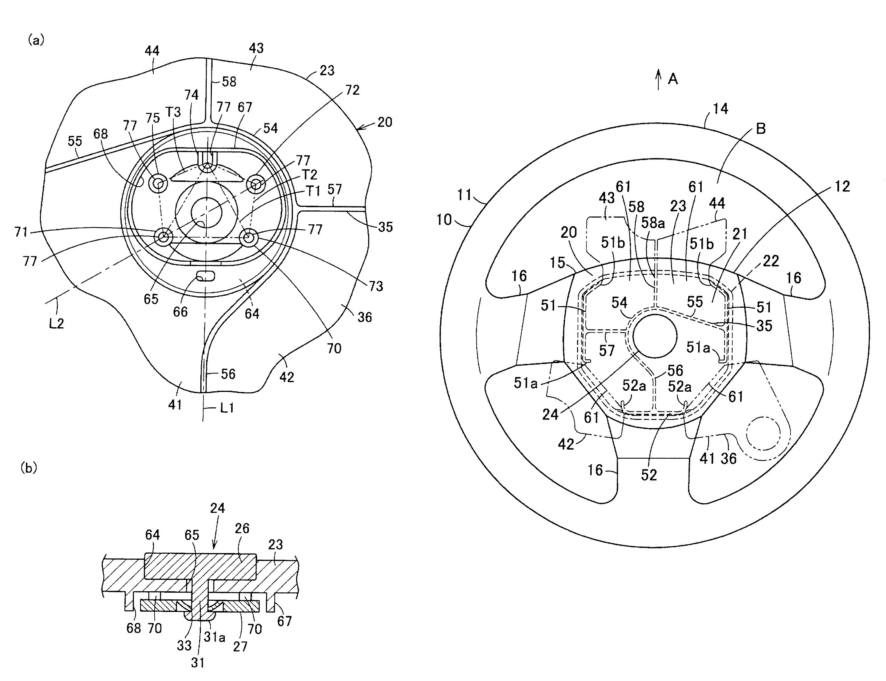
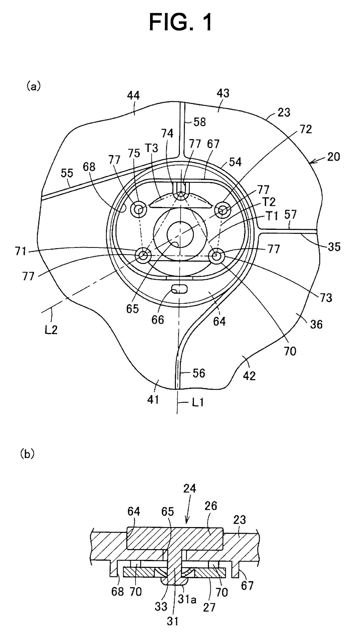
[0037]Hereinafter, a first embodiment of a cover member of an airbag device, according to the present invention, will be described referring to the drawings.

[0038]In FIG. 4, reference numeral 10 designates a steering wheel of an automobile (a vehicle). The steering wheel 10 includes a steering wheel body 11 and an airbag device 12 mounted on an occupant side of the steering wheel body 11. In addition, the steering wheel 10 is mounted on a steering shaft provided to a vehicle normally in an inclined state. However, it is noted that the following description will be provided with setting a straight-ahead state of a vehicle as a reference, setting a steering shaft side as a rear side, setting an occupant side as a front side, and setting a direction (a direction indicated by an arrow A) toward a front glass as an upper side.

[0039]The steering wheel body 11 includes a rim portion 14, which is a ring-like grip portion, a boss portion 15 positioned inside of the rim portion 14, and a plur...


PUM


Abstract

First support portions 71 and 72 positioned on a predetermined straight line L2 approximately perpendicular to a broken line of a hinge portion is set in a support portion 70 that supports a back plate 27 with respect to a back face side of a door portion 36. Second and third support portions 73 and 74 positioned in line symmetry with respect to the straight line L2, are set in the support portion 70. It is possible to receive the centrifugal force, which is applied to the back plate 27 due to the expansion of the door portion 36, with good balance by the first to third support portions 71, 72, 73, and 74. An emblem 24 can be reliably fixed to the door portion 36 with preventing a fixing pin 31 from being excessively locked into a through hole 33 more than necessary.

Description

CROSS REFERENCE TO RELATED APPLICATIONS[0001]This application claims priority of Japanese Patent Application No. 2012-104110 filed on Apr. 27, 2012. The contents of this application are incorporated herein by reference in their entirety.BACKGROUND OF THE INVENTION[0002]1. Field of the Invention[0003]The present invention relates to a cover member of an airbag device in which a plurality of door portions cleaved at the time of inflation and expansion of an airbag are segmented in a cover body covering the airbag.[0004]2. Description of the Related Art[0005]Conventionally, there has been used an airbag device provided in a fixed portion of a steering wheel of a vehicle such as an automobile. Such an airbag device includes an airbag substantially shaped like a bag, an inflator for supplying gas to the airbag, and a cover member for covering and accommodating the airbag at the time of non-expansion. In the cover member, a cover body covering the airbag accommodated in a retracted state ...

Claims


Application Information

Patent Timeline
Patent Type & Authority Patents(United States)
IPC IPC(8): B60R21/215B60R21/2165
CPCB60R21/2165B60R21/215B60R2021/21543
Inventor MURAMATSU, KATSUYASAKURAI, TOMOHIRO
Owner NIHON PLAST CO LTD
Why Eureka
Try Eureka