Structure for connecting crimping terminal and electric wire

a technology of crimping terminal and electric wire, which is applied in the direction of connection contact material, coupling base/case, and permanent deformation-induced connections, etc., can solve the problem of not being able to obtain waterproof performance, and achieve the effect of high density and waterproof performan

Inactive Publication Date: 2017-09-26
YAZAKI CORP
View PDF48 Cites 8 Cited by
  • Summary
  • Abstract
  • Description
  • Claims
  • Application Information

AI Technical Summary

Benefits of technology

[0018]According to the structure for connecting the crimping terminal and the electric wire of the configuration of (2), in the electric wire connection section of the caulked U-shaped sectional surface, since a pair of the caulking pieces are superimposed with each other, a tip section of one caulking piece which is superimposed becomes a lower side, and a tip section of the other caulking piece becomes an upper side. That is, in the electric wire connection section, which crimps the electric wire, the inside of the tip section of the other caulking piece is superimposed on and is caulked with the outside of the tip section of one caulking piece. The waterproof material provided on the waterproof material facing a surface which is the inside of the electric wire connection section, is pinched between the outside of the tip section of one caulking piece and the inside of the tip section of the other caulking piece. The waterproof material, which is disposed between the outside of the tip section of one caulking piece and the inside of the tip section of the other caulking piece, is moved in a direction to be extruded outward by pressure from the inside of the caulked electric wire connection section. At this time, protrusion of the waterproof material to the outside is suppressed by the bulged and deformed section entering and remaining at the recess, which is recessed and provided on the inside of the tip section of the other caulking piece. Accordingly, after caulking, a space between the outside of the tip section of one caulking piece and the inside of the tip section of the other caulking piece is reliably watertight-sealed with the waterproof material, and the water is less likely to infiltrate to the inside of the electric wire connection section from a joint.
[0020]According to the structure for connecting a crimping terminal and an electric wire of the configuration of (3), the waterproof material which is compressed by being caulked using the electric wire connection section is moved to a conductor tip side and a sheath crimping side along an extending direction of the electric wire in the inside of the electric wire connection section. At this time, protrusion of the waterproof material from the conductor tip side edge section to the outside is suppressed, by the bulged and deformed section entering at the recess formed on the conductor tip side edge section of the electric wire connection section. In addition, protrusion of the waterproof material from the sheath crimping side edge section to the outside is suppressed by the bulged and deformed section entering at the recess formed on the sheath crimping side edge section of the electric wire connection section. As a result, the waterproof material can remain with high density in the inside of the electric wire connection section.
[0021]According to the structure for connecting a crimping terminal and an electric wire according to the invention, waterproof performance can be sufficiently exerted by the waterproof material.

Problems solved by technology

In this case, if the water stop sheet is excessively extruded, there is a concern that the water stop sheet is not present in a position where the water is required to be stopped, and waterproof performance cannot be obtained.

Method used


Image

  • Structure for connecting crimping terminal and electric wire
  • Structure for connecting crimping terminal and electric wire
  • Structure for connecting crimping terminal and electric wire

Examples


Embodiment Construction

[0029]Hereinafter, an embodiment according to the invention will be described with reference to drawings.

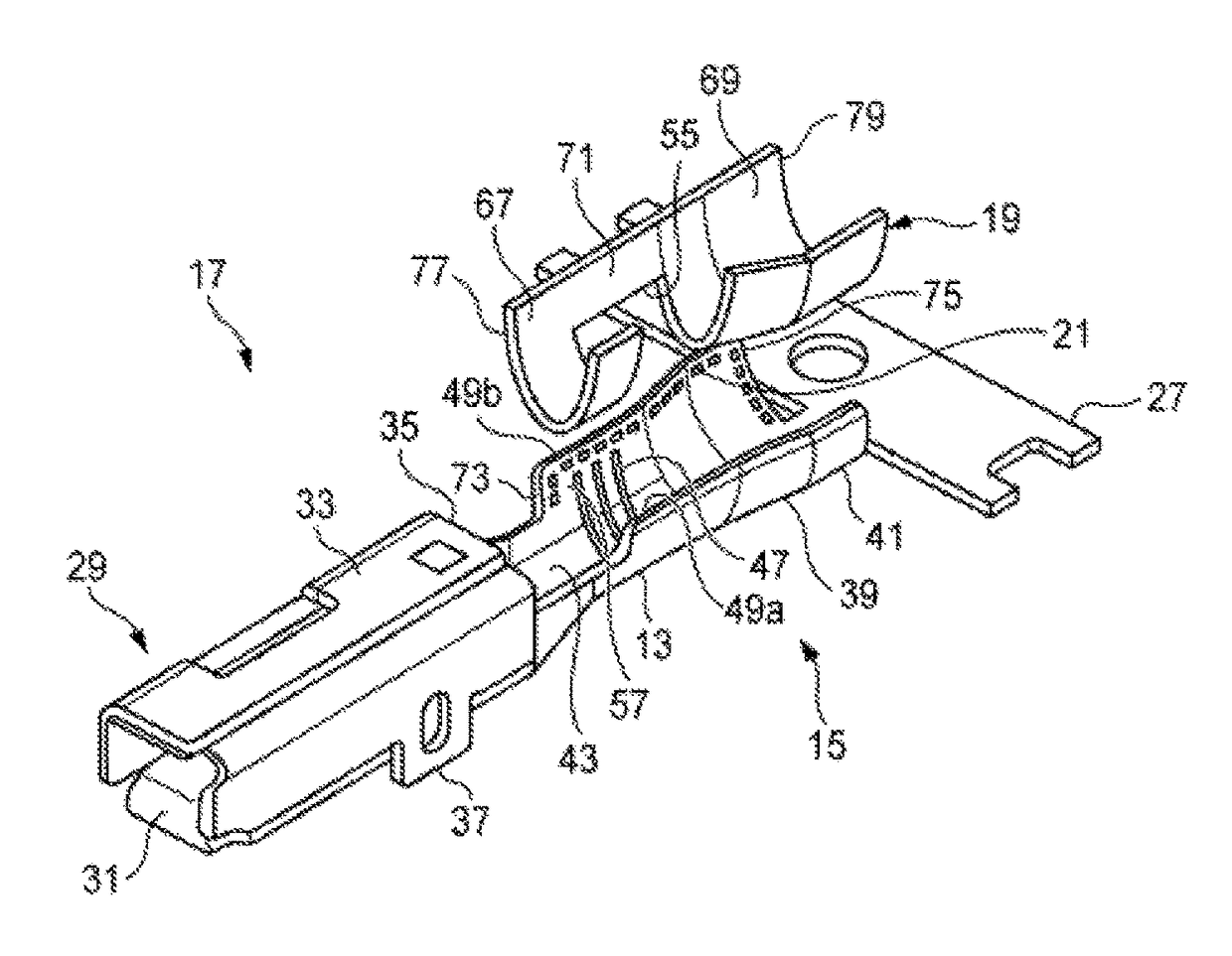
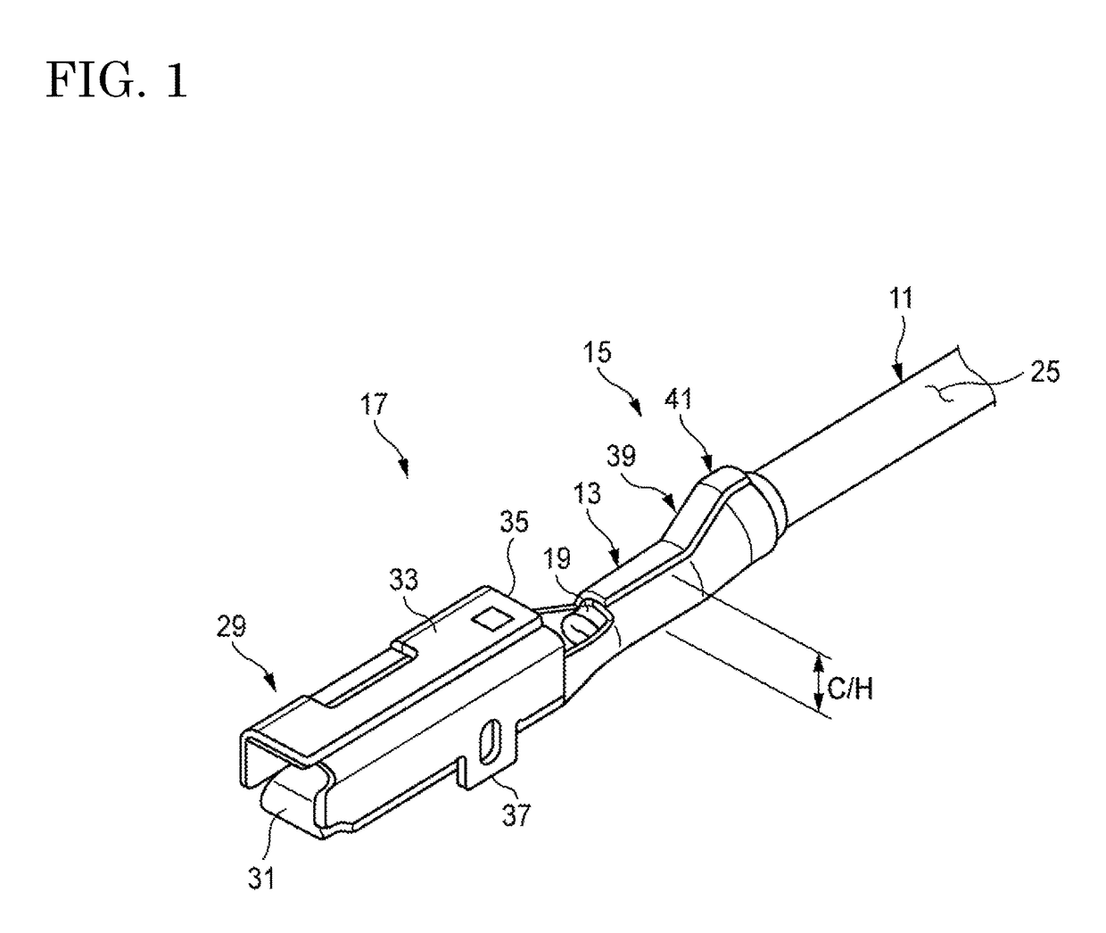
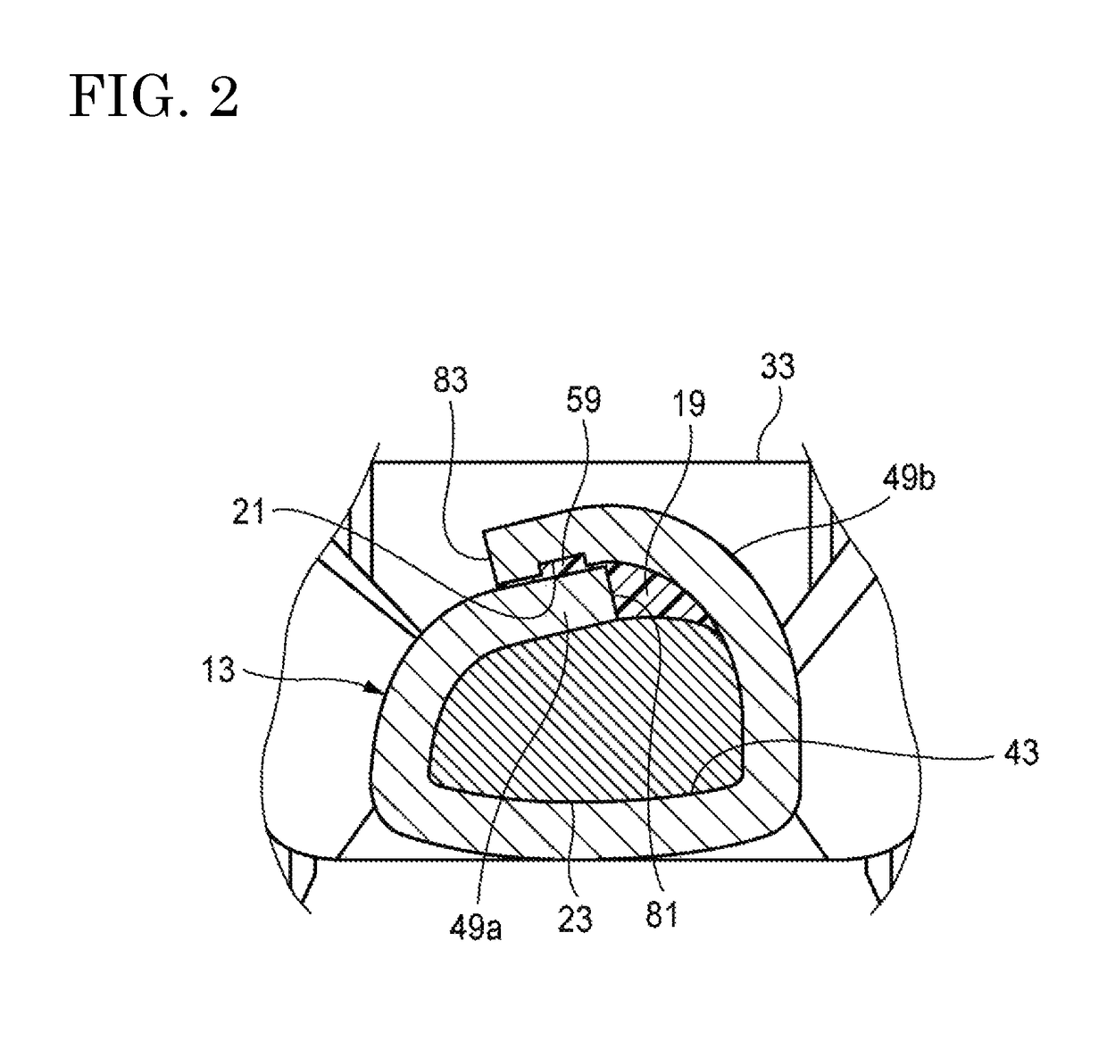
[0030]As illustrated in FIG. 1 to FIG. 3, a structure for connecting a crimping terminal and an electric wire according to an embodiment of the invention is provided with an electric wire 11, a crimping terminal 17, a water stop sheet 19 which is a waterproof material, and recesses 21.

[0031]In the electric wire 11, a conductor 23 is covered with an insulating sheath 25. The conductor 23 is constituted by a plurality of stranding element wires. Also, the conductor 23 may be a single line. In the conductor 23, for example, aluminum or aluminum alloy is used. In the sheath 25, synthetic resin is used. As the synthetic resin, for example, resin in which flame retardant is added to polyvinyl chloride (PVC), polyolefin, or polyamide as a base can be used.

[0032]The crimping terminal 17 is formed by a press process (punching process and a bending process) from a metal plate of one sheet ...


PUM


Abstract

A structure for connecting a crimping terminal and an electric wire, includes: the crimping terminal that is provided with an electric wire connection section to be crimped to the electric wire, the electric wire connection section including a conductor crimping section and a sheath crimping section which are successively disposed to each other; a waterproof material that includes an opening for allowing the conductor and the conductor crimping section to make contact with each other, has a size to surround the conductor and the sheath which are to be crimped, and is installed between the electric wire connection section and the electric wire; and a recess that is formed on at least one of the electric wire connection section and the sheath, and a bulged and deformed section of the waterproof material deformed by the electric wire connection section which is caulked and crimped enters.

Description

CROSS REFERENCE TO RELATED APPLICATIONS[0001]This application is a continuation of PCT application No. PCT / JP15 / 060287, which was filed on Mar. 31, 2015 base on Japanese Patent Application (No. 2014-077835) filed on Apr. 4, 2014, the contents of which are incorporated herein by reference.BACKGROUND OF THE INVENTION[0002]1. Field of the Invention[0003]The present invention relates to a structure for connecting a crimping terminal and an electric wire.[0004]2. Description of the Related Art[0005]A reduction in weight of a vehicle exerts significant influence on fuel efficiency. At the present time, when carbon dioxide emission is required to be reduced, particularly, in electric vehicles or hybrid vehicles in which a wire harness is used more than gasoline vehicles, it is convenient that an electric wire made of aluminum or aluminum alloy of lightweight material is used for the wire harness. However, if water is interposed to contact sections of both of the electric wire and a termina...

Claims


Application Information

Patent Timeline
Patent Type & Authority Patents(United States)
IPC IPC(8): H01R4/18H01R4/62H01R13/52H01R4/70
CPCH01R4/185H01R4/62H01R4/70H01R13/52H01R4/188
Inventor AOKI, HIROSHIOHTAKA, KAZUTO
Owner YAZAKI CORP
Why Eureka
Try Eureka