
Housing for an electronic device

a technology for electronic devices and housings, which is applied in the direction of electrical apparatus casings/cabinets/drawers, instruments, computing, etc., can solve the problems of inconvenient assembly and repair of computers, complicated configuration and arrangement of internal components of computers, etc., and achieves the enhancement of convenience for users or repair personnel in assembling and disassembling electronic devices and easy sorted cables/wires.

Inactive Publication Date: 2008-01-31
AOPEN
View PDF24 Cites 31 Cited by
  • Summary
  • Abstract
  • Description
  • Claims
  • Application Information

AI Technical Summary

Benefits of technology

[0007]Therefore, the object of the present invention is to provide a housing for an electronic device that facilitates sorting of cables / wires and that can be easily disassembled.
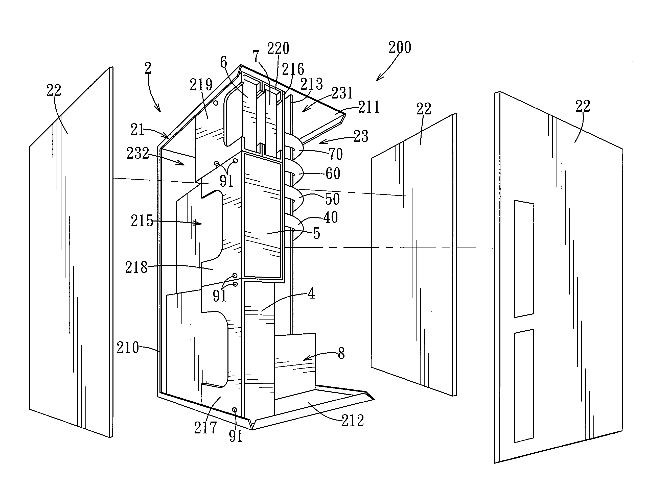
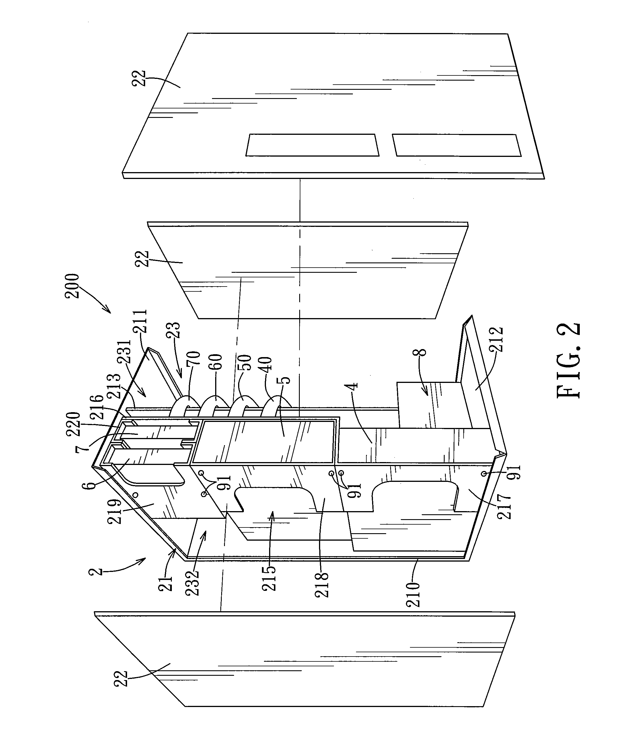
[0014]The housing for an electronic device according to the present invention utilizes the partition plate to permit disposition of the motherboard and the data devices respectively in the first and second receiving compartments. With the addition of the first and second positioning members, the cables are positioned at the left side face of the partition plate, and can extend through the wire sorting space to be plugged into the motherboard, while the second and third power supply wires are likewise positioned at the left side face of the partition plate. Therefore, the convenience in assembling and disassembling the electronic device by users or repair personnel is enhanced, and the cables / wires are easily sorted.

Problems solved by technology

Due to the ever increasing demand on performance capability and computing speed in computers, the configuration and arrangement of internal components in computers are becoming more complicated and more concentrated.
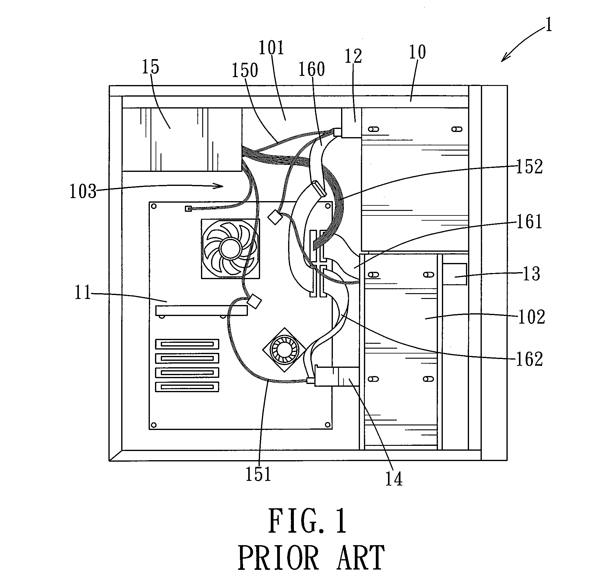
Therefore, cables and power supply wires between the internal components are increasing in number and becoming more concentrated as well, causing inconvenience during assembly and repair of the computers.

Method used


Image

  • Housing for an electronic device
  • Housing for an electronic device
  • Housing for an electronic device

Examples


Embodiment Construction

[0024]Before the present invention is described in greater detail, it should be noted herein that like elements are denoted by the same reference numerals throughout the disclosure.

[0025]Shown in FIG. 2, FIG. 3 and FIG. 4 is an electronic device incorporating the first preferred embodiment of a housing according to the present invention. The electronic device 200 includes a tower-type housing 2, and a motherboard 3, first, second, third and fourth data access devices 4, 5, 6, 7, and a power supply 8 disposed in the housing 2. The first data access device 4 is a rewritable digital versatile disk (DVD-RW) drive, the second data access device 5 is a read-only digital versatile disk (DVD) drive, the third data access device 6 is a hard disk drive (HDD), and the fourth data access device 7 is a floppy disk drive (FDD). It should be noted herein that the housing 2 is not limited to a tower-type housing, and can be a desktop-type housing in other embodiments of the present invention.

[0026]...


PUM


Abstract

A housing for an electronic device is adapted for disposition of a motherboard, a plurality of data access devices, and a plurality of cables. The housing includes a housing body and a partition plate. The housing body defines a receiving space. The partition plate is disposed in the housing body, and divides the receiving space into a first receiving compartment adapted for receiving the motherboard, and a second receiving compartment adapted for receiving the data access devices. The partition plate has a side edge cooperating with the housing body to define a wire sorting space that is in spatial communication with the first and second receiving compartments. The wire sorting space allows the cables that are connected electrically between the motherboard and the data access devices to pass therethrough. Consequently, convenience during assembly or disassembly by users or repair personnel is improved, and easier organization of the cables / wires is possible.

Description

CROSS-REFERENCE TO RELATED APPLICATION[0001]This application claims priority of Taiwanese Application No. 095127284, filed on Jul. 26, 2006.BACKGROUND OF THE INVENTION[0002]1. Field of the Invention[0003]The invention relates to a housing for an electronic device, more particularly to a housing that facilitates sorting of cables / wires of the electronic device.[0004]2. Description of the Related Art[0005]Due to the ever increasing demand on performance capability and computing speed in computers, the configuration and arrangement of internal components in computers are becoming more complicated and more concentrated. Therefore, cables and power supply wires between the internal components are increasing in number and becoming more concentrated as well, causing inconvenience during assembly and repair of the computers. As shown in FIG. 1, a conventional computer 1 normally includes a motherboard 11 fixed uprightly to a side wall 101 of a housing 10 at an inner side of the side wall 10...

Claims


Application Information

Patent Timeline
Patent Type & Authority Applications(United States)
IPC IPC(8): H05K5/00
CPCG06F1/184G06F1/181
Inventor HUANG, CHIA-CHIA
Owner AOPEN
Learn More